- Catalogs
- Hypro Pressure Cleaning
- Foam Marker OIPM
Foam Marker OIPM
1 /20Pages

Foam Marker OIPM
1 /20Pages
Catalog excerpts

ATTENTION! Read the instructions contained in this manual carefully. Hypro/ARAG cannot be held liable for damage caused by improper installation or use or non-observance of the general regulations for protection and safety at work. Foaming agents may be hazardous due to their toxicity! Never use the foam marker in enclosed or poorly ventilated places without wearing the appropriate Individual Protection Devices.Keep this manual with the foam marker. Opening the tank cap may cause foaming agent to suddenlycome out!This symbol draws special attention to operations where itis necessary to: cut offthe...
Open the catalog to page 2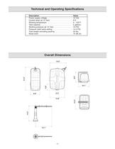
Technical and Operating Specifications > DescriptionValue Power supply voltage . . . . . . . . . . . . . . . . . . . . . . . . .12 Vdc Current draw (at 12 Vdc) . . . . . . . . . . . . . . . . . . . . . .9 A Working temperature . . . . . . . . . . . . . . . . . . . . . . . . .0 - 104F Tank capacity . . . . . . . . . . . . . . . . . . . . . . . . . . . . . . .5 gallons Working pressure (at 12 Vdc) . . . . . . . . . . . . . . . . . .10 PSI Pressure relief valve setting . . . . . . . . . . . . . . . . . . . .14.5 PSI Total weight excluding packing . . . . . . . . . . . . . . . . .40 lbs. Noise level...
Open the catalog to page 4
Precautions: When installing the foam marker, it is necessary to observe a few essential rules. Secure the electric compressor unit in a position sheltered from stones picked up by the wheels or by the productssprayed from the booms.ՕOn seeders, install the electric compressor unit sheltered from areas that are too dusty. Using the clamps supplied, fit the air-liquid foam nozzles at the end of the booms at a distance from the last nozzleequal to half the distance of the spray tips. The foam must fall in an area sheltered from the nozzle, and the point where it falls must mark the area sprayed...
Open the catalog to page 5
The electric compressor and tank can be mounted on the machine in two different ways (see illustration at left). Option 1 When joining the electric compressor unit DӔ to the foaming liquid tank A,Ӕ place the spacers BӔ and fixing bracket CӔ between them. Option 2 Install the compressor unit DӔ and the tank AӔ in different locations according to your own needs. In this case, it is possible to secure the bed of theelectric compressor to the machine, or to use the bracket CӔ. The foam nozzle or air-liquid mixers must bemounted at the end of the booms as follows:On boom ՓA, make 2 holes at a center...
Open the catalog to page 6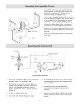
Mounting the Liquid/Air Circuit > Connect the white hoses (air) and the dark bluehoses (liquid) to the mixing sprayer farthest from the electric compressor unit, making sure the hoses and fittings are the same color.Lay the hoses along the framework of the boom asfar as the electric compressor unit, allowing extraby the hinges. Connect the hoses to the electric compressor, respecting the hose/fitting coloring.Connect the closest foam nozzle to the electriccompressor unit, repeating the above procedure.Connect the dark blue hoses (liquid) and the whitehoses (air) to the fittings of the same color...
Open the catalog to page 7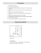
1.Put some liquid in the tank.2.Fully screw the cap onto the tank. 3. Start the electric compressor positioning the selector (AӔ on illustration below)on the right.4.After a few seconds, check that the liquid is coming out of the right-hand foamnozzle.5.Check the correct seal of the hydraulic couplings. 6.Shift the selector to the left (AӔ on illustration below) and repeat operations4and 5.7.Stop delivery by positioning the selector to OFF (middle). 8. Discharge the remaining pressure from the tank as shown on page 2 .9.Empty the water from the tank.10.Clean the circuit as described in the maintenance...
Open the catalog to page 8
Starting and Operation Start up the compressor with the lever selector A, onthe control panel. After a few seconds, the circuit will reach its working pressure, making foam come out of the selected foam nozzle.ՕAdjust the intensity of the foam outlet, using the flow-rate regulator on the tank cap.During use, it is possible to alternate the right- or left-hand foam nozzle by moving the selector lever.ՕTo stop operation of the foam marker, turn the selectorlever to the OFF position (middle).To finally stop the supply to the foam marker, turn thestarter key to the OFF position (if the electrical...
Open the catalog to page 9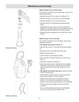
Machine down for up to seven days For periods of inactivity of up to seven days, carry out thefollowing operations:Slacken the band ՓB and remove the diffusor ԓA. ԕRemove the grid CӔ by turning it counterclockwise. Take the sponge ՓD out of the foam nozzle. ԕCarefully wash the foam diffusers and sponge withwater.Reassemble the parts. Use care when inserting thesponge as it must go freely into its seat without crushing, which would alter the operation of the foam marker.ՕRepeat the above operations for the other foam nozzleas well. Machine down for up to 30 days For periods of inactivity of up...
Open the catalog to page 10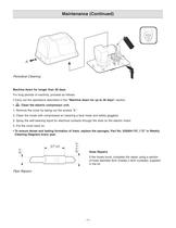
Toensure dense and lasting formation of foam, replace the sponges, Part No. 520004-747, (ՓD in WeeklyCleaning Diagram) every year. > Machine down for longer than 30 days 1. Remove the cover by taking out the screws ԓA. 2. Clean the inside with compressed air (wearing a face mask and safety goggles). 3. Spray the self-cleaning liquid for electrical contacts through the slots on the electric motor. 4. Put the cover back on. ԓMachine down for up to 30 days section. For long periods of inactivity, proceed as follows: ԕCarry out the operations described in the Clean the electric compressor unit: Hose...
Open the catalog to page 11
PROBLEMCAUSEREMEDY The electric compressor will notwork. The pilot lights fail to come on.-No power reaches theconsole.-Check the fuse.-Check the electrical connections of theconsole.The electric compressor will notwork. The pilot lights come on.-Electrical connection betweencontrol unit and electric compressor broken.-Check the connections between thecontrol box and the electric compressor.No foam comes out of the foamnozzles.-The tank will not pressurize.- Close the tank cap properly.-Check the tightness of the hosesconnecting the compressor with the cap. Foam formation is not good.- Sponge...
Open the catalog to page 16All Hypro Pressure Cleaning catalogs and technical brochures
 PRODUCT CATALOG
236 Pages
 Transfer Pumps
7 Pages
 Gear Driven
3 Pages
 Centrifugal Pumps
41 Pages
 9302 Series
2 Pages

Archived catalogs
 DBS & DBA Diaphragm Pump OIPM
20 Pages
 Series 2100 Versa-Twin OIPM
16 Pages
 Hydraulic Pressure Washer OIPM
20 Pages
 Hydraulic Pump Selection Guide
38 Pages
 9302 Series Sales Sheet
2 Pages
 UAS Ceramic Nozzles
2 Pages
 HP Stainless Steel Nozzles
2 Pages
 TwinCap Sales Sheet
2 Pages
 ULD Sales Sheet
2 Pages
 ESI Sales Sheet
2 Pages
 Series 5300 OIPM
20 Pages
 2535S OIPM
12 Pages
 PowerLine Plunger OIPM
24 Pages
 Cleanload OIPM
12 Pages
 Series 5200 Piston Pump OIPM
8 Pages


- Pump
- Industrial pump
- Pump with electric motor
- Centrifugal pump
- Self-priming pump
- Chemical pump
- Control valve
- Water valve
- Stainless steel pump
- Transfer pump
- Diaphragm pump
- Pressure gauge
- Piston pump
- Pressure limiter
- Hydraulic pump
- Single-stage pressure regulator
- Materials handling pump
- Cast iron pump
- Industrial pressure limiter