- Catalogs
- Smiths Interconnect
- Modular Connectors
- Company
- Products
- Catalogs
- News & Trends
- Exhibitions
Modular Connectors
1 /27Pages

Modular Connectors
1 /27Pages
Catalog excerpts
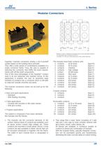
5.508.2511.00A11.00 Therefore a stepӔ is defined as the length used by each assembled element.- An elementary step is defined as 5.50 mm- The letter AӔ is the sum of the dimensions of the contact elements. Hypertac > modular connectors employ a do-it-yourselfsystem based on the building block principle. They offer a wide variety of combinations available in a single connector frame. Thus, the user is capable of selecting the connector that fulfills the exact require- ments with off-the-shelf components. One of the many advantages of the Hypertac > ή contactused is its low extraction and insertion forces. In this application it enables the user to assemble large numbers of contacts into a connector which is still able to mate and unmate smoothly and easilyThe modular connectors series can be built up for thefollowing:?Rack and panel applications-Standard -With floating mounting?Cable applications-Hooded with rounded or flat cable clamps -With jack screws?Program applicationsThe system is composed of two basic elements:the modules and the frames.1.The modules are the connector elements of thesystem. Various types of contacts are available, such as signal, power, coaxial, high voltage, etc. These contacts are mounted in small plastic blocks. Crimp contacts are also available in plastic blocks that can be mounted individually or together into the frame. The width of each module block is designated in steps. The modules have fixed contacts with:2contacts@ 50 amps(type M) 2contacts@ 25 amps(type C) 2 contactsshielded(type E) 2contactshigh voltage(type H) 1contact@ 200 amps(type I) 2 contactsfiber optic(type Y) 3contacts@ 15 amps(type B) 4contacts@ 15 amps(type N) 5contacts@ 8 amps(type A) 9 contacts@ 5 amps(type Q) 9 contacts@ 8 amps(type G)17contacts@ 5 amps(type D)Coaxial contacts:2contacts(type J) 2contacts(type K) 3contacts(type L)Removable contacts:2contacts@ 25 or 50 amps(type Z) 3contacts@ 15 amps(type W) 5contacts@ 8 amps(type T) 5contacts@ 8 amps(type X)17contacts@ 8 amps(type O) 30contacts@ 3 amps(type LW)2.They range from a basic frame consisting of 2 siderails and 2 end caps to more complex versions with jack screws, hoods, cable clamps, etc. All frames are available in numerous lengths to conform to almost any combination of modules. With the modular Series, specially designed connec- tors can be purchased quickly and inexpensively, eliminating the extra cost and delay of custom tooling. > APRIL 2005 235 >
Open the catalog to page 1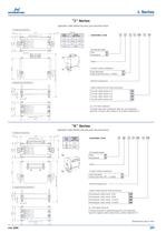
J SERIES PLUG CONNECTOR 7.60 A+16 7.60 SPECIAL element progression cableclamp lenght(size A+16) ORDERING CODE > cable clamp Plug P Receptacle E > PJ Series Element progression > EJ Contact surface treatmentGold StandardGold as per MIL-DTL- C 55302 > 53.00 HT > mated connector: 73.00 J SERIES RECEPTACLE CONNECTOR Cable clamp (only for Plug connector)Circular cable clamp 24 Circular cable clamp 踸 10 10 > 12.00 11.00 Circular cable clamp 15 15 > 7.50 Circular cable clamp 20 20 > M3 24 > 5 4 3 K SERIES PLUG CONNECTOR 7.60 A+16 7.60 element progression cable clamplegth ORDERING CODE > PK Plug P Receptacle...
Open the catalog to page 3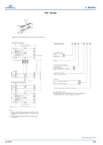
BV SERIES PLUG CONNECTOR with extractor 2 and 0: A+24element progression ORDERING CODE > 4 2 3 5 Plug P > male guide pinfemale guide socket Receptacle E Series Element progressionbefore screw extractor Contact surface treatmentGold StandardGold as per MIL-DTL- 55302 HT > M3 extractor 2 and 0: 52.20 8.50 11.00 12.00 mated connector: 84.70 Extractor see note 1 BV SERIES RECEPTACLE CONNECTOR Type 2: standard (2 steps) 2 Type 0: special (2 steps) > 12.00 11.00 Element progression after screw extractor > 8.50 M3 female guide socket
Open the catalog to page 5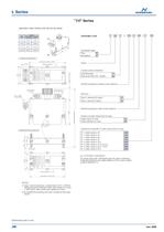
cable minimum size of connectorChoice B clamp ORDERING CODE > Plug P Receptacle E > JV SERIES PLUG CONNECTOR element progressionwith extractor 2 and 0: A+27.0012.50 Series Element progression before screw extractor > ABC Contact surface treatmentGold StandardGold as per MIL-DTL- 55302 > 1 1 21 2 3 37.6034.00 HT > 2 3 54 extract. 2 e 0: 22.20 cable clampRef. B: with one second cable clampRef. B: location of Extractor of cable clampRef. A: Position Type 2: standard (2 steps) 2 Type 0: special (2 steps) Element progression after screw extractor > 53.00 Position of cable clamp (only for plug) Cable...
Open the catalog to page 6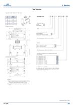
cable PKV EKV clamp lengthminimum(A+27.00/A+32.50) ORDERING CODE > 131.5095.75 Plug P Receptacle E > KV SERIES PLUG CONNECTOR with extractors 2 and 0 A+27.00 element progression Series Element progression before screw extractor > ABC Contact surface treatmentGold StandardGold as per MIL-DTL- 55302 > 1 1 21 44.30mated connector: 84.7053.00 HT > 2 3 37.6034.00 2 3 54 Extractor extrc. 2 e 0: 22.20 Type 2: standard (2 steps) 2 Type 0: special (2 steps) Element progression after screw extractor Quantity and dimensions of rectangular cable clamp(only for plug)N > KV SERIES RECEPTACLE CONNECTOR N 1...
Open the catalog to page 7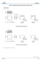
2 STEPS: 11mm. > (assembly with spacer clips) 1725 1m9 10.7513.00 1.50蘘1.401.00(hole)(hole)ؘ1.300.90 > Guide pin Guide pin 6.40 INSULATING BLOCK: Ref. LWMHT Ref. LWMRRef. LWMS (AWG28 ط 22)(AWG22)22.00 CONTACTS ARE SUPPLIED SEPARATE > 1f 9 1725 10.75 Guide socket Guide socket 13.00 1.45ؘ1.00(hole)(hole)0.90ؘ1.30 22.00INSULATING BLOCK: Ref. LWFHT Ref. LWFRRef. LWFS (AWG28 22)(AWG22) CONTACTS ARE SUPPLIED SEPARATE For spare parts ordering codes: consult factory Dimensions are in mm > APRIL 2005 >
Open the catalog to page 11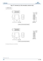
2 STEPS: 11mm. > (assembly without spacer clips) 1712 m17 61 11.0022.00 6.80 29.00 1.80蘘2.45(hole) INSULATING BLOCK: Ref. OHm Ref. ORm (AWG20 16) CONTACTS ARE SUPPLIED SEPARATE > f17 61 11.0022.00 1712 29.00 2.45瘘1.80(hole) INSULATING BLOCK: Ref. ORf (AWG20 16) Ref. OHf CONTACTS ARE SUPPLIED SEPARATE For spare parts ordering codes: consult factory Dimensions are in mm >
Open the catalog to page 12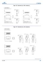
(assembly without spacer clips) 1.10 踸1.10 > (hole) (hole) 5.50 5.50 59 43 2 1876 E P 4 162378 95 4.50 4.50 22.00 22.00 Ref. Qm Ref. Qm > 13.00 13.00 1.10 1.10 INSULATING BLOCK: Ref. QHP > (hole) INSULATING BLOCK: Ref. QHE > (hole) NOTES: NOTES: -The codes are for elements mountedon plug connectors.-For spare elements the code must befollowed by the letter P ex. QHP, QmP, QfP-The codes are for elements mountedon receptacle connectors.-For spare elements the code must befollowed by the letter E ex. QHE, QmE, QfE 4.50 4.50 Ref. Qf Ref. Qf > (assembly with spacer clips) > m17 10.75 12 3 45 611109871213...
Open the catalog to page 13All Smiths Interconnect catalogs and technical brochures
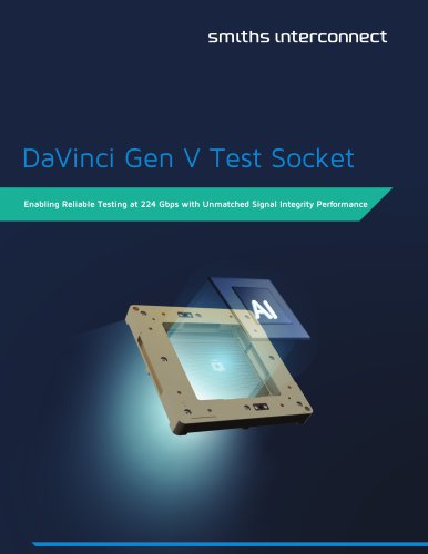 DaVinci Test Socket Gen V
4 Pages
 QN-Series
2 Pages
 R-Series H-Pin® Socket
2 Pages
 Q-Series H-Pin® Socket
2 Pages
 M-Series H-Pin® Socket
2 Pages
 K Series H-Pin® Socket
2 Pages
 ESJ Series H-Pin Socket
2 Pages
 ES Series H-Pin® Socket
2 Pages
 D Series H-Pin® Socket
2 Pages
 H-Pin Brochure
28 Pages
 C-Series H-Pin® Socket
2 Pages
 ARINC 801
4 Pages
 Optical Backplane Connectors
2 Pages
 Coaxial Couplers Brochure
12 Pages
 Micro-D Twinax
8 Pages
 Micro Quadrax/Twinax Catalog
10 Pages
 Rugged D-Sub
14 Pages
 NDL-T/NDL-Q Miniature Triax
16 Pages
 HYPERGRIP
12 Pages
 Diamond Rf Resistives®
10 Pages
 Lab-Flex® S Series
6 Pages
 Semi-Rigid Cable Brochure
12 Pages
 Planar X RF Filters
4 Pages
 HBB Catalog
36 Pages
 N Series Catalogue
21 Pages
 REP Series Brochure
8 Pages
 KM Series catalog
35 Pages
 KNB/KNC/KND Series Catalog
46 Pages
 HDLP Catalogue
16 Pages
 LightConex Series
5 Pages
 HR CTX Brochure
6 Pages
 Optical FMC Cards
2 Pages
 LightVISION 10G VM Series
2 Pages
 SNAP12
2 Pages
 Volta Series
6 Pages
 K2TVA Series
4 Pages
 TS06 Series
5 Pages
 CTX Series
5 Pages
 CEX Series
9 Pages
 M23 Industrial Catalogue
72 Pages
 Intercompact PCB
8 Pages
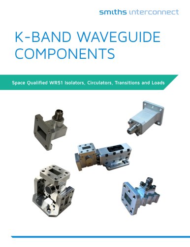
 K-Band Passive Components
12 Pages
 BOA Series
8 Pages
 NXS Series
12 Pages
 TSX Fixed Chip Attenuators
4 Pages
 Galileo Test Socket
3 Pages
 HDC Heavy Duty Connectors
42 Pages
 LR Series
52 Pages
 L Series Catalogue
32 Pages
 Thermocouple Spring Probes
4 Pages
 0.020” & 0.030” Centers
7 Pages
 0.156” & 0.187” Centers
5 Pages
 0.050” Centers
12 Pages
 0.187” Centers
5 Pages
 Component Catalog
102 Pages
 SNAP12
2 Pages
 LightVISION VM
2 Pages
 SH-100 & SHE-100 Se
8 Pages
 100563 Coax Series
6 Pages
 SS-30 Series
45 Pages
 Quad-00 Series
4 Pages
 D Series
16 Pages
 Resistor Family
10 Pages
 SpaceNXT™ AURORA Series
8 Pages
 SpaceNXT™ Ku Series
8 Pages
 Interposers
12 Pages
 SpaceNXT™ Q Series
6 Pages
 KuStream 2000 Antenna System
4 Pages
 Dovetail Brochure
4 Pages
 2mm cPCI Catalog
16 Pages
 TT9 SMT Brochure
6 Pages
 Lab-Flex T Series
6 Pages
 Transformer Range Brochure
16 Pages
 TT9 SMT Series Brochure
6 Pages
 B Series Catalogue
24 Pages
 C Series
32 Pages
 C9394
C939436 Pages
 Coax Contacts
7 Pages
 Filters and Diplexers
4 Pages
 K Series Catalogue
76 Pages
 KA series
44 Pages
 M12 Circular W Series
40 Pages
 M23 Stainless Steel
48 Pages
 M40 Circular P Series
16 Pages
 M58 Series Catalog
20 Pages
 MHD Catalog
36 Pages
 Nebula Series
8 Pages
 SCX Coax
9 Pages
 Triax Contacts
13 Pages
 mDCX & mDHC ConneCtorS
9 Pages
 LHS LHZ LHT Series
36 Pages
 Standard coaxial connector
7 Pages
 Eclipta Edge Card Brochure
8 Pages
 Micro Series
7 Pages
 Filter Rack & Panel Catalog
17 Pages
 Filter D-Subminiature Catalogue
18 Pages
 Filter Circular Catalog
24 Pages
 CMD Catalogue
64 Pages
 C150 & C153 CONNECTOR SERIES
36 Pages
 C SERIES sPrinG PrOBes
8 Pages
 LSH Brochure
4 Pages
 LHS Catalogue
23 Pages
 KVPX Brochure
4 Pages
 KS Catalogue
4 Pages
 Hyperstac Datasheet
2 Pages
 HPH Catalogue
24 Pages
 HeavyPower Brochure
6 Pages
 C160 Datasheet
2 Pages
 C128 Datasheet
2 Pages
 C55 Datasheet
2 Pages
 Backplane Twinax Brochure
6 Pages
 KMC Catalogue
25 Pages
 2mm cPCI Brochure
6 Pages
 VME64X Catalogue
12 Pages
 HPW Catalogue
24 Pages
 HPD & HPF CONNECTOR SERIES
36 Pages
 CMD CONNECTOR SERIES
64 Pages
 Standard Spring Probes
16 Pages
 C153
C15336 Pages
 MIL-DTL-38999 Quadrax/Twinax
10 Pages
 M58 Circular V Series
2 Pages
 M23 Circular S Series
2 Pages
 Circulaires filtrés
24 Pages
 Quadsplitter
8 Pages
 Filtered D-sub connector
18 Pages
 N series
24 Pages


Archived catalogs
 Filtered Adapter
1 Page
 DO Series
2 Pages
 AST
AST2 Pages
 BST
BST5 Pages
 HDC / KDC
23 Pages
 CI-D
CI-D3 Pages
 KLC
KLC6 Pages
 KJB
KJB5 Pages
 CSC
CSC8 Pages
 KB
KB17 Pages
 HD
HD8 Pages
 Single Pole Power Connectors
2 Pages
 Heavy Duty Modular Connectors
25 Pages
 Rack Panel connector
5 Pages
 Single Pole Power Connectors
2 Pages


- Smiths Interconnect data connector
- Smiths Interconnect electrical power supply connector
- Smiths Interconnect metal connector
- Smiths Interconnect round connector
- Smiths Interconnect plastic connector
- Smiths Interconnect industrial connector
- Smiths Interconnect screw-in connector
- Socket electrical connector
- Smiths Interconnect IP67 connector
- Smiths Interconnect circular connector
- Smiths Interconnect rectangular connector
- Male connector
- Current connector
- Smiths Interconnect straight connector
- Smiths Interconnect electronic filter
- Smiths Interconnect transceiver
- Optical cable
- Smiths Interconnect cable harness
- Copper connector