
Catalog excerpts

DAS ZEICHEN DER HYDROPA GRUPPE WEGEVENTILE NG 10 • pmax bis 350 bar • Qmax bis 140 l/min • Anschlussmaße gemäß DIN 24340 und ISO 4401 DIRECTIONAL CONTROL VALVES NOMINAL SIZE 10 • pmax up to 350 bar • Qmax up to 140 l/min • Installation dimensions acc. to DIN 24340 and ISO 4401 Hydropa GmbH & Cie. KG Därmannsbusch 4 • D-58456 Witten Postfach / P.O. Box 31 65 • D-58422 Witten Telefon / Telephone (0 23 02) 70 12-0 Telefax (0 23 02) 70 12-47 Internet: www.hydropa.de • E-Ma
Open the catalog to page 1
Wegeventile NG 10 Typ WE 10 AH Directional control valves nominal size 10 type WE 10 AH FUNCTIONAL DESCRIPTION Das Wegeventil WE 10 AH besteht im Wesentlichen aus dem Ventilgehäuse (1), dem Steuerkolben (5) mit zwei Zentrierfedern (4) und -je nach Anwendung-ein oder zwei Elektromagneten (2 + 3) als Betätigungselemente. Wegeventile mit drei Schaltstellungen besitzen zwei Elektromagnete und zwei Zentrierfedern. Wegeventile mit zwei Schaltstellungen sind entweder mit einem Elektromagnet und einer Rückführfeder oder zwei Elektromagneten und einer Rasteinrichtung ausgestattet. Durch die...
Open the catalog to page 2
Wegeventile NG 10 Typ WE 10 AH Directional control valves nominal size 10 type WE 10 AH ORDERING CODE Sofern keine anderen Angaben im Klartext angegeben sind, werden die Wegeventile mit Standard-Gerätesteckern nach DIN 43 650 und Standard-Nothandbetätigung ausgeliefert. Weitere Spannungen und Gerätestecker sind auf Anfrage lieferbar. If there are no other information specified in clear text, the directional control valves are delivered with standard electrical connectors according to DIN 43 650 and standard manual overrides. Further voltages and electrical connectors are available upon...
Open the catalog to page 3
Directional control valves nominal size 10 type WE 10 AH FUNCTIONAL SYMBOLS Spool classification F1 - Three positions (a, 0, b) with spring centering Spool type Change-over position of spool Spool classification F4 - Two positions (a, 0) with spring centering Spool type Change-over position of spool
Open the catalog to page 4
Wegeventile NG 10 Typ WE 10 AH Directional control valves nominal size 10 type WE 10 AH FUNCTIONAL SYMBOLS Kolbenanordnung F5 - 2-Stellungsventile (0, b) mit Federzentrierung Spool classification F5 - Two positions (0, b) with spring centering Kolbentyp Spool type Schaltzeichen Symbol Kolbendarstellung mit Übergangsposition Change-over position of spool Kolbenanordnung E2 - 2-Stellungsventile (a, b) mit Federendlage Spool classification E2 - Two positions (a, b) with spring offset Kolbentyp Spool type Schaltzeichen Symbol Kolbendarstellung mit Übergangsposition Change-over position of spool...
Open the catalog to page 5
Wegeventile NG 10 Typ WE 10 AH Directional control valves nominal size 10 type WE 10 AH ALLGEMEINE KENNGRÖSSEN GENERAL CHARACTERISTICS Bauart Design Schieberventil Sliding spool valve Einbaulage Mounting position beliebig optional Befestigungsart Type of mounting Plattenaufbau nach ISO 4401, CETOP 05 Subplate body according to ISO 4401, CETOP 05 Anschlüsse P A, B , Ports P A, B , Max. Betriebsdruck Max. operating pressure Flüssigkeit Fluid Mineralöl nach DIN 51524 Mineral oil acc. to DIN 51524 Umgebungstemperaturbereich Ambient temperature range Viskositätsbereich Viscosity range Max....
Open the catalog to page 6
Wegeventile NG 10 Typ WE 10 AH Directional control valves nominal size 10 type WE 10 AH p-Q-CHARACTERISTIC CURVES Kennlinien A: Grenzkurven der vom Wegeventil übertragenen maximalen Hydraulikleistung Characteristic curves A: Operating limits for maximum hydraulic power transferred by the directional valve Kennlinien B: Druckverlust in Abhängigkeit vom Volumenstrom Characteristic curves B: Pressure drop related to flow rate KENNLINIEN A CHARACTERISTIC CURVES A Betriebsdruck p / Working pressure p [bar] Kolbentyp Spool type Durchflussrichtung / Flow direction P-A 40 60 80 100 120 Volumenstrom...
Open the catalog to page 7
Wegeventile NG 10 Typ WE 10 AH Directional control valves nominal size 10 type WE 10 AH Gleichspannungsspule, Ausführung für Gerätesteckdose gemäß DIN 43 650 DC-Coil, design for connector according to DIN 43 650 STANDARD EQUIPMENT Gleichspannungspule mit integriertem Gleichrichter, Ausführung für Gerätesteckdose gemäß DIN 43 650 DC-Coil with integrated rectifier, design for connector according to DIN 43 650 ELECTRICAL CONNECTORS SPECIAL FUNCTIONS MANUAL OVERRIDES Mit Gummischutzkappe Bei Einsatz elektromagnetischer Wegeventile im Freien oder unter tropischen Klimabedingungen sollte die...
Open the catalog to page 8
Wegeventile NG 10 Typ WE 10 AH Directional control valves nominal size 10 type WE 10 AH Mitgelieferte Schrauben: 4 Schrauben M6 x 40 DIN 912-10.9 (Anzugsmoment 14+2 Nm) Dichtringe: 5 O-Ringe 12,42 x 1,68 (NBR) oder 5 O-Ringe 12,42 x 1,68 (Viton) Delivered bolts: 4 bolts M6 x 40 DIN 912-10.9 (Tightening torque 14+2 Nm) Seal rings: 5 O-rings type 12,42 x 1,68 (NBR) or 5 O-rings type 12,42 x 1,68 (Viton) Betätigungsmagnet a Betätigungsmagnet b Nothandbetätigung Typenschild O-Ring 12,42 x 1,68 4 Ventilbefestigungsbohrungen Befestigungsmutter des Elektromagneten Gerätesteckdose nach DIN 43 650...
Open the catalog to page 9
Wegeventile NG 10 Typ WE 10 AH Directional control valves nominal size 10 type WE 10 AH INSTALLATION DIMENSIONS T Erforderliche Oberflächengüte des Gegenstücks Required surface finish of interface • Bei Geräteeinsatz außerhalb der im Katalog angegebenen Werte bitten wir um Rücksprache • In cases of operation which differ from the data given in this brochure please consult us • Bei Wegeventilen mit zwei Elektromagneten kann jeder von beiden erst nach Ausschalten des anderen eingeschaltet werden. • For directional control valves with two solenoids, one solenoid must be powered down before the...
Open the catalog to page 10
Und so finden sie uns: And so you find us: Herbede Münster / Recklinghausen Blockventile / Block valves Anlagen / Units Bochum - Stiepel Witten - Herbede Druckschalter / Pressure switches Pumpen / Pumps Hydraulikzylinder / Hydraulic cylinder Innovativer Systempartner der Industrie - KOMPETENT - FLEXIBEL - QUALITÄTSORIENTIERT Innovative systempartner of the industry - COMPETENT - FLEXIBLE - QUALITY
Open the catalog to page 11All Hydropa catalogs and technical brochures
-
 Data sheet HYC-Series
20 Pages
-
 Data sheet HYKS-Series
20 Pages
-
 Data sheet MPF 100
3 Pages
-
 Data sheet MPF 030
3 Pages
-
 Data sheet Accessiors
34 Pages
-
 Data sheet ZA6RE
1 Pages
-
 Data sheet ZAH6-R
4 Pages
-
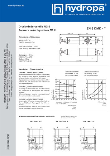 Data sheet ZN6DMD
1 Pages
-
 Data sheet ZN6DB-VS AB
1 Pages
-
 Data sheet ZN6DB-VS A/B/P
1 Pages
-
 Data sheet ZN6DB
1 Pages
-
 Data sheet ZN6DR
4 Pages
-
 Data sheet WE10AH
11 Pages
-
 Data sheet WE6AH
14 Pages
-
 Data sheet SPA/SPG pumps
9 Pages
-
 Datenblatt DS-104 / EX
8 Pages
-
 Data sheet DS-802
2 Pages
-
 Datenblatt DS-4*7 / 4*2
10 Pages
-
 Data sheet DS-507/502
8 Pages
-
 Data sheet DS-307/302
8 Pages
-
 Data sheet DS-117/112
8 Pages
-
 Data sheet HY-3.SM
16 Pages
-
 Overview special power packs
4 Pages
-
 Data sheet KA-Power packs
4 Pages
-
 DS-307 / 302
8 Pages
-
 DS-507 / 502
8 Pages
-
 DS-4*7 / 4*2
4 Pages
-
 HYDRAULIC CYLINDERS
20 Pages
-
 DS-117 / DS-112
8 Pages
-
 2 SPG
2 SPG9 Pages
-
 ZAH10 DR
1 Pages
-
 WE6AH
WE6AH14 Pages
-
 DMH-630 R
11 Pages
-
 Hand pumps
12 Pages
-
 ZN 6 DBS - * - AB
1 Pages
-
 ZA 6 RE -*
1 Pages
-
 Z 6 R *
1 Pages
-
 ZN 6 DMD - *
1 Pages
-
 ZN 6 DB - *
1 Pages
-
 ZN 6 DR-*
4 Pages
-
 3 SP-B
4 Pages
-
 2 SP-B
4 Pages
-
 1 SP-B
4 Pages
-
 DS-802/M/B
2 Pages
-
 DS-4*7/4*2
4 Pages
-
 DS-507 / DS-502
8 Pages
-
 DS-307 / DS-302
8 Pages
-
 Special - Power Packs
4 Pages
-
 KOMPAKT-AGGREGATE
4 Pages
-
 HYDRAULIC MOTORS
16 Pages
-
 ATEX-PRESSURE SWITCH
1 Pages
-
 SPECIAL POWER PACKS
4 Pages
-
 MINI POWER PACKS
12 Pages


Archived catalogs
-
 DS-117/112
8 Pages
-
 Rotary Actuators
16 Pages