- Catalogs
- DIEHL Metering
- Multi Jet Flow Sensor M-TXKA/M-THXKA
Multi Jet Flow Sensor M-TXKA/M-THXKA
1 /2Pages

Multi Jet Flow Sensor M-TXKA/M-THXKA
1 /2Pages
Catalog excerpts
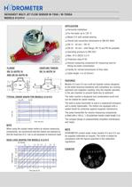
DATASHEET MULTI JET FLOW SENSOR M-TXKA / M-THXKA COUPLING THREAD TYPICAL ERROR GRAPH FOR MODELS 413/414 When using the contact water meters as volume measuring components, we recommend that the meters are selected so that the head loss of 0.1 bar is not exceeded at maximum load! HEAD LOSS GRAPHS FOR MODELS 413/414 □ Model 414 with carbide bearing □ Overall and connection dimensions to DIN ISO 4064 □ DN 20 - 40 mm - with flange, PN 16 and PN 40 available □ Volume measuring component for measuring heat for billing hot water consumption □ Facility for remote transmission of flow rates Models 413 and 414 are multi-jet impeller meters designed to the latest technical standards with completely dry running operation and magnetic coupling. Only the impeller operates in the wet chamber to prevent faults due to sediment. The roller counter is dustproof and condensation-proof and can be rotated for easier reading. The built-in pulse transmitter is cast in a waterproof enclosure and is easily replaceable. The meters are equipped with a sealed shield for protection against magnetic interference. The pulse transmitter for volume measuring components is fitted with a 100 Q, 74 W protective resistor (cable length 3 m) The compact design in subassemblies simplifies maintenance HYDROMETER contact water meter models 413 and 414 can be supplied calibrated on request. The meter is tested for compliance with the figures specified in the calibration
Open the catalog to page 1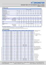
DATASHEET MULTI JET FLOW SENSOR M-TXKA / M-THXKA TECHNICAL DATA The M-T(H)XK Qn 6 (DN 32) is also available with G 11/. B meter thread to DIN ISO 4064. 'Manufacturer's note: Please read the note below the head loss graph before selecting suitable meter sizes. ORDER REFERENCES class indicated! Available pulse rates: Other versions and pulse rates Note - Please indicate separately when ordering: e.g. mechanical roller counters, order the pulse output without resistor type designations: □ HYDROMETER GmbH • Postfach 1462 • 91505 Ansbach/Germany □ Delivery address: IndustriestraBe 13 • 91522 AnsbaclYGermany...
Open the catalog to page 2All DIEHL Metering catalogs and technical brochures
 AERIUS
2 Pages
 CORONA_DP_405
5 Pages
 CORONA MCI COMPOSITE 108
3 Pages
 AQUILA V3 DIN
3 Pages
 AQUARIUS S / RS / P - MID
3 Pages
 CORONA E
9 Pages
 AQUILA V4
3 Pages
 CORONA MDI 110
5 Pages
 CORONA DP 405
5 Pages
 ALTAIR V4
3 Pages
 WESAN ST 215
3 Pages
 IZAR DOSING
2 Pages
 IR PULSE TRANSMITTER 573
3 Pages
 REED SWITCH 570
3 Pages
 IZAR PULSE H
2 Pages
 SIGNAL CONVERTER 520.11
4 Pages
 WESAN WP HE CHECK 725
3 Pages
 WESAN WP H 225
3 Pages
 WESAN WPV A 226/216
3 Pages
 ALTAIR V3
3 Pages
 CORONA ST 130
3 Pages
 CORONA P 423/424
5 Pages
 AQUARIUS S/RS/P
3 Pages
 Wesan WB E
5 Pages
 HYDRUS
8 Pages
 ALTAIR MCI 119
3 Pages
 WESAN WB 234
3 Pages
 WESAN WS 233
3 Pages
 Corona ER
8 Pages
 WESAN HP 225
3 Pages
 Altair
3 Pages
 Wesan
Wesan4 Pages
 corona
9 Pages
 SHARKY Model 775
6 Pages
 Sharky Model 773
10 Pages
 Ray Model
12 Pages
 energy calculator ENERGY-INT6
11 Pages
 bulk water meter model 725
2 Pages
 dry runner sheet model 118
2 Pages


- Flowmeter
- Volume flow monitor
- Liquid flow monitor
- In-line flow meter
- Water flow monitor
- Compact flow monitor
- Ultrasonic flow monitor
- Flange flow meter
- Low flow rate flow meter
- Positive displacement flow meter
- Analog water meter
- Digital water meter
- Rotary piston flow meter
- Dry dial water meter
- Residential water meter
- Wet dial water meter