


Standard Connector Series Main Catalogue

Standard Connector Series Main Catalogue
JAEGER Connecteurs specializes in interconnection systems, focusing on circular connectors for industrial applications. The company prioritizes quality, innovation, and customer service, catering to sectors such as automation, robotics, power, medical, automotive, marine, railway, and aerospace.
- Standard Series: Includes standard, high voltage, and thermocouple contact connectors.
- Rapid Series: Features rapid connectors with gold-plated contacts and high voltage options.
- Weatherproof Series: Offers weatherproof connectors with high-performance PG outlets.
- Hermetic Series: Comprises hermetic connectors for panel and bulkhead applications, including ultra-vacuum and push-pull types.
- Miniature Push-Pull Series: Includes Atto and Natto connectors, with high-performance options.
- Industrial Series: Features standard, weatherproof, and high-performance connectors, including those with mixed contacts.
- Marine and Neptunox Series: Designed for marine environments.
- Robotic Series: Includes connectors with mixed contacts for robotic applications.
- Minex Series: Offers specialized connectors for specific needs.
- Printed Circuits Series: Includes connectors for various miniature and industrial applications.
- Power Series: Features single-pole and multi-pole connectors for high current applications.
JAEGER connectors are designed with various IP protection ratings, ensuring resistance to dust and water. They are available with different contact arrangements and assembly options to meet specific industrial needs.
The document details accessories such as cable clamps, protective caps, gaskets, seals, and housings for panel connectors. It provides technical guides for assembly, wiring, and attachment of connectors.
JAEGER Connecteurs offers a comprehensive range of connectors and accessories, emphasizing adaptability and innovation to meet diverse industrial requirements.
The document provides detailed specifications and descriptions of various series of connectors with non-removable contacts, including Standard, Thermocouple, Rapid, Weatherproof, and Hermetic series. Each series is designed for specific applications and environments, offering different features such as locking mechanisms, contact types, and protection ratings.
This series is versatile and robust, featuring multi-pole connectors with 3 to 52 solder contacts, screw locking, and IP 50-54 protection. It includes rectangular housing with three possible cable outlets.
Designed for temperature measurement applications, this series includes multi-pole connectors with 3 solder contacts, screw locking, and IP 50-54 protection. It supports thermocouple types J, K, and T.
An evolution of the Standard Series, the Rapid Series features a quick locking system, available in gold-plated contact and high voltage versions. It offers multi-pole connectors with 3 to 17 solder contacts and IP 50-54 protection.
Suitable for environments exposed to water splashes, this series offers multi-pole connectors with 3 to 52 solder contacts, screw locking, and IP 65 protection. It includes circular housing and a high-performance version for stringent requirements.
Designed for vacuum environments, high pressure, and gas tightness, this series features multi-pole connectors with 3 to 52 solder contacts, screw locking, and a leak rate of 10-9 Atm. cm3/second with helium.
The document includes detailed technical data such as maximum current, contact resistance, breakdown voltage, insulation resistance, operating temperature, and materials used. It also provides dimensional data for various connector types and assemblies.
Recommendations for assembly and available accessories are provided, including protective caps, flat gaskets, and cable clamps. The document emphasizes that dimensions and specifications may change without prior notice.
- Flat-gaskets are used for panel connectors and come in packs of 10.
- Connectors are sealable and tamper-evident.
- Maximum conductor cross-section is 1.91 mm² for high-voltage cables.
- Materials include nickel-plated light alloy and silver-plated brass contacts.
- Operating temperature ranges from -40°C to +100°C, with a maximum of 500 hours at +125°C.
- Do not separate connector parts or fit/remove protective caps when the circuit is under load.
- Use shielded or unshielded high-voltage cables as specified.
- Follow assembly instructions strictly to achieve optimal performance.
- Types include J, K, T, S, and E, each with specific metal combinations and temperature ranges.
- Applications vary based on temperature range, resistance to pollution, and gas atmosphere compatibility.
- Contact resistance is less than 0.0015 Ω for ø 2 mm and varies for thermocouple ø 3 mm.
- Breakdown voltage exceeds 1500 Volts (RMS) between pins and ground.
- Insulation resistance is greater than 5000 MΩ.
- Dimensions and specifications are subject to change without notice.
- Various connector types and configurations are available, including rapid series with gold-plated contacts.
- Ensure polyethylene insulating sleeves are fully inserted.
- Refer to technical guides for detailed assembly and wiring instructions.
- Connector Types: Circular and square male panel connectors, female cable connectors, and male coupler connectors.
- Contact Options: Available with 3 to 52 contacts, with diameters of 2 mm, 3 mm, and 4 mm.
- Materials: Brass with olive-green cadmium surface treatment, gold-plated brass contacts, and PBT insert.
- Protection: IP 65 rating with flat-gasket for panel connectors.
- Operating Temperature: -40 °C to +100 °C, with a maximum of 500 hours at +125 °C.
- Max Current: 15 A for ø 2 mm, 35 A for ø 3 mm, and 50 A for ø 4 mm contacts.
- Contact Resistance: Less than 1.5 mΩ for ø 2 mm, less than 1 mΩ for ø 3 mm, and less than 0.7 mΩ for ø 4 mm.
- Breakdown Voltage: Greater than 2500 Volts (RMS) between adjacent contacts and greater than 1500 Volts (RMS) between peripheral contacts and ground.
- Insulation Resistance: Greater than 5000 MΩ.
- Includes moulded watertight rubber boots for cables, which must be mounted in the cable connectors or coupler connectors.
- Instructions for assembly, wiring, and contact arrangement are available in technical guides.
- Additional accessories are listed in the accessories section.
- For connectors with 4 contacts ø 4 mm, contact No. 4 can be used as a ground contact.
- Specifications and dimensions are subject to change without prior notice.
- Connectors are available with 3 to 52 contacts, with diameters of 2 mm, 3 mm, and 4 mm.
- Maximum current ratings are 7 A for 2 mm, 12 A for 3 mm, and 20 A for 4 mm contacts.
- Helium leak rate is less than 10-9 Atm.cm³/sec, with a permissible constant pressure difference of 50 bars and a maximum test pressure of 150 bars.
- Contact resistance is less than 4 mΩ for 2 mm, less than 3 mΩ for 3 mm, and less than 1.5 mΩ for 4 mm contacts.
- Insulation resistance exceeds 10000 MΩ, and breakdown voltage between adjacent contacts is over 1500 Volts (RMS) at ~100Pa.
- Operating temperature ranges from -50 °C to +125 °C, with some components rated for 500 hours at +150 °C.
- Gold-plated steel body and Dilver P contacts for some connectors.
- Nickel-plated light alloy and silver-plated brass contacts for others.
- Sintered glass insulation between pins and body ensures mechanical resistance.
- Connectors are compatible with standard and weatherproof cable connectors.
- Moulded watertight rubber boots are provided for cable connectors.
- Assembly, wiring, and installation instructions are available in technical guides.
- Protection levels range from IP 50 to IP 65, depending on the associated cable connector and use of elastomer or flat-gasket seals.
- Locking mechanisms include screw connections and locknuts.
- Various accessories are available, including protective caps and replacement parts like seals, nuts, and locknuts.
- Dimensions and specifications are subject to change without prior notice.
- For detailed assembly and contact arrangement instructions, refer to the technical guides.
- Standard Series: Includes female cable connectors with options for protective caps and different types of cable clamps.
- Weatherproof Series: Offers female cable connectors with small and large outlet cable clamps, suitable for harsh environments.
- Natto Miniature Push-Pull Series: Features connectors designed for frequent locking and unlocking, with options for protective caps and cable clamps.
- Contacts: Available in 3 to 7 contacts with options for non-removable solder contacts or removable solder/crimp contacts.
- Current and Voltage: Maximum current of 5 A with a breakdown voltage of over 350 Volts (RMS).
- Mechanical Endurance: Rated for 50,000 locking and mating cycles.
- Environmental Resistance: IP65 protection with flat-gasket for panel connectors, helium leak rate of less than 10-9 Atm.cm³/sec, and permissible pressure differences up to 50 bars.
- Temperature Range: Operating temperatures from -25°C to +125°C, with short-term exposure up to +150°C.
- Nickel-plated steel body with gold-plated contacts for durability and corrosion resistance.
- Sintered glass insulation for mechanical resistance.
- Conductors are attached by tin soldering, with recommendations to avoid thermal shocks.
- Technical guides are available for detailed assembly, wiring, and installation instructions.
- Weatherproof Connectors: These include male cable connectors and male coupler connectors, available in standard and high-performance versions. They are designed for durability in harsh environments.
- Hermetic Panel Connectors: These are circular male panel connectors that can be attached by welding or locknut, ensuring a secure and sealed connection.
- Rapid Connectors: Square male and female panel connectors with gold-plated contacts, designed for quick and reliable connections.
- Miniature Push-Pull Series: Compact and high-performance connectors with push-pull locking, suitable for applications requiring multi-pole connections.
- Industrial Series: Robust connectors available in weatherproof and high-performance versions, designed for harsh environments with multi-pole capabilities.
- Marine and Neptunox Series: Designed for underwater and harsh environments, offering excellent corrosion resistance and weatherproofing up to 10 bars.
- Robotic Series: Robust connectors designed to withstand impacts and vibrations, suitable for large diameter cables and mixed contact configurations.
- Power Series Puissance: High-current connectors designed to carry up to 300 A, with options for circular and rectangular configurations.
- Multi-pole configurations with various contact options (solder/crimp).
- Locking mechanisms include push-pull and 1/6 turn click locking.
- IP ratings ranging from IP 50 to IP 68, indicating varying levels of protection against dust and water.
- Materials used include ARCAP and 303 stainless steel for corrosion resistance.
- Dimensions and specifications are subject to change without prior notice.
- The document includes a numerical index for connectors with non-removable contacts.
- Atto Miniature Push-Pull Series: Features multi-pole connectors with 3 to 7 solder/crimp contacts, screw connection, and IP 65 protection. Made from POM/PBT plastic material, suitable for numerous applications.
- Natto Miniature Push-Pull Series: Offers connectors with 3 to 55 solder contacts, suitable for printed circuits with screw connection, push-pull, or 1/6 turn click locking. Protection ranges from IP 50 to 65.
- Atto Series: Includes panel, cable, and coupler connectors with circular housing, push-pull locking, and IP 65 protection. Supports 7 to 27 contacts with a maximum current of 5 A. Operating temperature ranges from -40°C to +100°C.
- Natto Series: Similar configurations with additional options for high-performance applications, supporting up to 19 contacts with varying diameters (1 mm, 1.6 mm, 2.4 mm) and higher current capacities (7 A to 30 A). Operating temperature ranges from -55°C to +200°C.
- Series: Miniature and Weatherproof Miniature with ground contact.
- Connector Types: Panel, cable, and coupler connectors available in rectangular and circular housings.
- Locking Mechanism: Knurled ring on cable connector, 1/6 turn on panel connector barrel for frequent locking/unlocking.
- Protection Rating: IP 50 to IP 54 for Miniature Series, IP 65 for Weatherproof Miniature Series with flat-gasket.
- Contacts: 12 to 55 contacts, ø 1 mm, crimp or solder removable contacts.
- Max Current: 7 A for ø 1 mm contacts.
- Mechanical Performance: 1000 locking and mating cycles.
- Contact Resistance: Less than 0.0020 Ω between pin and socket.
- Breakdown Voltage: At 20 °C, sea-level: 19 or 37 contacts >2000 Volts (RMS), 12, 27, or 55 contacts >2500 Volts (RMS).
- Insulation Resistance: Greater than 5000 MΩ.
- Operating Temperature: -40 °C to +100 °C, with 500 hours at +125 °C.
- Materials: Nickel-plated light alloy, gold-plated brass contacts, neoprene insert.
- Housing: Square and circular options available.
- Contact Diameter: 1 mm, with soldered and crimped options (0.6 mm² to 0.93 mm²).
- Tools: Complete crimp tool and tool for insertion/removal of contacts available.
- Protective Caps: Available for panel, cable, and coupler connectors.
- Flat-Gasket: Provided for panel connectors (pack of 10).
- Polarisation Systems: Available to prevent incorrect connections.
- All contacts must be mounted using the specified tool.
- Dimensions and specifications are subject to change without notice.
- Connector Types: Male cable connectors, female coupler connectors, and panel connectors are available in various configurations.
- Protection Ratings: Connectors offer protection ranging from IP50 to IP68, depending on the series and configuration.
- Contact Options: Available with 3 to 37 contacts, with diameters of 1 mm, 1.6 mm, and 2.4 mm. Contacts can be crimped or soldered.
- Current and Voltage: Maximum current ratings are 7 A for 1 mm contacts, 15 A for 1.6 mm contacts, and 30 A for 2.4 mm contacts. Breakdown voltage exceeds 2500 Volts (RMS).
- Materials: Connectors are made from nickel-plated light alloy, gold-plated brass contacts, and neoprene inserts.
- Temperature Range: Operating temperatures range from -40 °C to +100 °C, with some series offering extended ranges.
- Crimp tools and positioners are specified for contact insertion and removal.
- Assembly and wiring instructions are provided in technical guides.
- All contacts must be mounted using the specified tools.
- Consult technical guides for detailed assembly and installation instructions.
- For high-performance versions and improved temperature ranges, consultation is advised.
Circular housing with locking screw connection and IP 68 protection using a flat-gasket for panel connectors. The connectors support various contact sizes: 7 to 19 contacts of 0.76 mm, 3 to 37 contacts of 1 mm, 3 to 12 contacts of 1.6 mm, and 3 to 7 contacts of 2.4 mm. Contacts are removable and can be crimped or soldered. Maximum current ratings are 5 A for 0.76 mm, 7 A for 1 mm, 15 A for 1.6 mm, and 30 A for 2.4 mm contacts. Contact resistance is less than 3mΩ for 1 mm, less than 2mΩ for 1 mm, less than 1.5mΩ for 1.6 mm, and less than 1mΩ for 2.4 mm contacts. The connectors can withstand immersion up to 10 Bar and have a breakdown voltage of over 1500 V (RMS) for 0.76 mm, over 2000 V (RMS) for 1 mm, and over 2500 V (RMS) for 1.6 mm and 2.4 mm contacts. Insulation resistance is greater than 5000 MΩ, and the operating temperature range is -40 °C to +100 °C. Materials include 303 stainless steel, gold-plated brass contacts, and neoprene inserts.
Assembly involves using specific crimp tools and positioners for different contact sizes. For 0.76 mm contacts, use crimp tool 630 180 006 with positioner 769 100 006. For 1 mm contacts, use crimp tool 579 316 006. For 1.6 mm and 2.4 mm contacts, use crimp tool 579 481 006. Tools for insertion and removal of contacts are also specified.
All connectors are delivered with their contacts, and specific tools must be used for mounting contacts in the insert. Connectors can be fitted with an ethylene propylene insert for power applications. Thermocouple contacts can also be fitted. For detailed assembly, wiring, and installation instructions, refer to the technical guides.
Includes flat-gaskets for panel connectors, cable glands with varying capacities, and protective caps for panel, cable, and coupler connectors. Specific part numbers are provided for different configurations and accessories.
Dimensions and specifications are subject to change without notice. The document provides detailed dimensional data for various connector configurations, including square panel connectors, cable connectors, and coupler connectors.
- Connectors are available with both removable and non-removable contacts.
- Protection level is IP 65 with a flat-gasket for panel connectors.
- Contacts include 17 mixed contacts: 13 contacts of ø 1 mm and 4 contacts of ø 2.4 mm, with options for crimp or solder removable contacts.
- Max current: 7 A for ø 1 mm and 30 A for ø 2.4 mm contacts.
- Operating temperature ranges from -40 °C to +100 °C, with a maximum of 500 hours at +125 °C.
- Materials used include nickel-plated alloy, gold-plated brass contacts, and neoprene inserts.
- Crimp tool with positioner 579 481 006.
- Tools for insertion and removal of contacts: ø 1 mm (597 104 006), ø 1.6 mm (577 454 006), ø 2.4 mm (577 458 006).
- Protective caps and flat-gaskets are available for panel, cable, and coupler connectors.
- All contacts must be mounted using the specified tool.
- Assembly, wiring, and installation instructions are available in the technical guides.
- Thermocouple contacts can be fitted as per accessory guidelines.
- Dimensions and specifications are subject to change without prior notice.
- Detailed dimensional data is provided for various connector types, including robotic and Minex series.
- Female contact No. 1 can be used as a ground contact and is connected by a green/yellow wire to the barrel of the connectors.
- All connectors are delivered with their contacts.
- For additional accessories and technical data, refer to the respective sections in the document.
1. Removable crimp contact with a diameter of 12 mm, supporting a maximum current of 300 A.
2. Contact resistance between pin and socket is less than 0.02 mΩ for ø 12 mm.
3. Insulation resistance exceeds 10000 Volts (RMS).
4. Breakdown voltage between contact and housing is greater than 3000 Volts (RMS).
5. Mechanical endurance is rated for 10000 locking and mating cycles.
6. Operating temperature ranges from -40 °C to +100 °C, withstanding 120 hours at +120 °C.
7. Salt spray resistance is 240 hours.
8. Materials include light alloy with black anodising, silver-plated brass contacts, and polyoxymethylene (POM) insert.
9. Maximum cross-section of crimped conductors is 95 mm², with a reducer required for 70 mm² cross-section.
1. Crimp tool 809 875 006 with crimp jaws 809 912 006 is used for ø 12 mm contacts.
2. Tool for insertion and removing contacts is 896 903 006.
3. For assembly, wiring, panel connector installation, and contact arrangement, refer to technical guides.
1. Circular male panel connectors, female cable connectors, and male coupler connectors are available.
2. Cable clamps are available in types D and E, with specific part numbers for different diameter ranges.
3. Flat-gaskets and protective caps are available for panel and cable connectors.
4. All connectors are delivered with their contact, and dimensions/specifications may change without notice.
1. Connectors with non-removable and removable contacts are available.
2. Important to use the specified tool for mounting contacts in the insert.
3. For 35 mm² contacts, a class 6 extra-flexible cable is recommended, with a reducer needed for class 5 flexible cables.
1. Crimp Tools: Use 809 835 006 with crimp jaws 809 909 006 for ø 8 mm and 579 481 006 crimp tool with positioner for ø 1.6 mm.
2. Contact Tools: Tool for insertion and removing contacts is 806 903 006.
3. Cable Clamps: Circular housing options include D: 809 605 006 for ø 20 to ø 32 mm and E: 809 625 006 for ø 20 to ø 25 mm.
4. Panel Connector: Delivered with a flat-gasket, 4 screws, 4 washers, and 4 nuts.
5. Cable Recommendations: For 35 mm² contacts, use class 6 extra-flexible cable; for class 5, add a reducer.
6. Contact Mounting: All contacts must be mounted using the specified tool.
7. Connectors: Delivered with contacts; dimensions and specifications may change without notice.
1. Max Current: 175 A.
2. Contact Resistance: < 0.03 mΩ for ø 8 mm.
3. Insulation Resistance: > 10000 MΩ.
4. Breakdown Voltage: > 3000 Volts (RMS).
5. Mechanical Endurance: 10000 locking and mating cycles.
6. Operating Temperature: -40 °C to +100 °C (120 hours at +120 °C).
7. Salt Spray Resistance: 240 hours.
8. Materials: Light alloy, black anodising, silver-plated brass contacts ø 8 mm, gold-plated brass contacts ø 16 mm, polyoxymethylene (POM) insert.
9. Max Cross-Section: 25 mm² cross-section crimp directly; 16 mm² requires a reducer.
1. Circular and Rectangular Multi-Pole Connectors: 25 mm² connectors with 175 A capacity.
2. Panel, Cable, and Coupler Connectors: Available in circular and rectangular forms.
3. Locking Mechanism: Screw connection with IP 65 protection using flat-gasket for panel connector.
1. Flat-Gasket: Available in packs of 10 for round and square connectors.
2. Protective Caps: For both panel and cable connectors.
3. Assembly Instructions: Refer to technical guides for detailed assembly, wiring, and installation instructions.
4. Additional Accessories: See accessories section for more options.
- Housing 1: 3 to 7 contacts with diameters of 1.6 mm and 2.4 mm.
- Housing 2: 12 to 37 contacts with diameters of 1 mm and 1.6 mm.
- Housing 3: 12 to 27 contacts with diameters of 1.6 mm.
- Housing 5: Single and multi-pole connectors with diameters of 8 mm and 12 mm.
- Standard and Rapid Series: Instructions for assembling panel and cable connectors, including removing cable sheaths, stripping wires, and soldering contacts.
- Weatherproof Series: Steps for assembling weatherproof connectors, emphasizing the use of weatherproof boots and integral cable clamps.
- Miniature Push-Pull Series: Detailed steps for assembling connectors with removable contacts, including the use of insertion tools.
- Contact diameters and configurations for each housing type.
- Assembly diagrams showing the correct orientation and placement of components.
- Disassemble the cable connector and slide the cable through the clamp, housing, and boot.
- Strip the cable wires and solder or crimp them to contacts.
- Insert wired contacts into the connector barrel using an insertion tool.
- Assemble the housing and tighten the cable clamp screws.
- Similar steps as the Weatherproof Series with additional components like cone and seal holder.
- Ensure proper insertion of contacts and assembly of components in the circular housing.
- Includes assembly for connectors with 17 mixed contacts.
- Use half-shells for housing and ensure correct placement of grooves and components.
- Apply heat to thermo-adhesive sheath for secure sealing.
- Focuses on the use of coupling, claw, and seal in assembly.
- Ensure correct insertion of contacts and secure assembly with the connector barrel.
- Involves additional components like bushings and ground contacts.
- Emphasizes the use of specific tools for screwing bushings and securing ground contacts.
- Always refer to the wiring document for detailed instructions on soldering and crimping.
- Ensure all contacts are correctly identified and inserted according to the wiring diagram.
- Use appropriate tools for assembly to ensure secure and reliable connections.
- Diagrams illustrate the correct assembly sequence and placement of components.
- Tables provide dimensions and specifications for panel connectors and housing attachments.
The document provides detailed instructions on adjusting and using a crimp tool. To select the correct position, press the positioner and lock your choice, remove the safety pin, lift the selector knob, and turn it to align the selected number with the indexing mark. Refit the safety pin after adjustment. This process should be repeated whenever the wire or contact diameter changes. It is crucial to adjust the positioner and selection knob when the tool is in the open position.
The document includes a table listing wire and contact specifications, including diameters, AWG sizes, cross-sections, and corresponding positioner and selection knob positions. For example, a wire with a diameter of 0.76 mm and AWG 26 has a cross-section of 0.15 mm² and uses positioner 3.
To crimp a contact, first strip the wire and adjust the crimp tool. Insert the stripped wire into the contact shaft, ensuring full insertion via the vent hole. Open the crimp tool fully, insert the contact and wire assembly into the tool's orifice, and crimp by closing the tool's arms completely until it reopens. Verify the crimp by checking that the wire is visible through the vent hole and the insulation is against the contact's rear.
The document lists various tools and accessories, including part numbers for crimp tools, positioners, and tools for fitting and removing contacts. It also provides specifications for reducers and other accessories used in wiring and contact assembly.
Instructions for fitting and removing contacts are provided. To fit contacts, use blade No. 2, position the wire and contact in the channel, and insert from the rear of the connector. To remove contacts, use blade No. 1 or No. 3, apply axial pressure to release the pin or socket.
The document includes a numerical index of technical guides and part numbers for various tools and accessories related to wiring and contact assembly.
Catalog excerpts

STANDARD CONNECTOR SERIES
Open the catalog to page 1
JAEGER CONNECTEURS Connect to Innovation
Open the catalog to page 2
The JAEGER values Quality „Quality attracts attention“, E. JAEGER (1924). This has been the motto of the entire company for almost 60 years, contributing to our customers’ satisfaction. Innovation Innovation comes from listening to your needs. This is why JAEGER founded VINCI, its „Smart Industrial and Commercial intelligence“, working group, the role of which is to integrate the latest cuttingedge technologies into our products. Service Our priority at JAEGER Connecteurs is customer satisfaction. Our sales department offers technical solutions adapted to your needs. Constantly adapting At JAEGER...
Open the catalog to page 3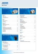
Connectors with non-removable contacts Connectors with removable contacts Standard Series - Standard . . . . . . . . . . . . . . . . . . . . . . . . . . . . . . . . . . . . . . . . . . . . . . . . . . . . . . . . . . . . . . . . 10 - Standard High Voltage . . . . . . . . . . . . . . . . . . . . . . . . . . . . . . . . . . . . . . . . . . . . . . . . . . . . . . 12 - Standard with thermocouple contacts . . . . . . . . . . . . . . . . . . . . . . . . . . . . . . . . . . . . . . . . . . . 14 Miniature Push-Pull Series - Atto Miniature Push-Pull . . . . . . . . . . . . . . . . . . . . . . . . . ....
Open the catalog to page 4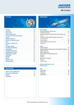
Technical guides Cable clamps . . . . . . . . . . . . . . . . . . . . . . . . . . . . . . . . . . . . . . . . . . . . . . . . . . . . . . . . . . . . . 106 Protective caps . . . . . . . . . . . . . . . . . . . . . . . . . . . . . . . . . . . . . . . . . . . . . . . . . . . . . . . . . . 110 Gaskets and seals . . . . . . . . . . . . . . . . . . . . . . . . . . . . . . . . . . . . . . . . . . . . . . . . . . . . . . . . 115 Contact arrangement - Standard, Rapid, Weatherproof and Hermetic Series . . . . . . . . . . . . . . . . . . . . . . . . . . . - Atto Miniature Push-Pull Series . . . . . . ....
Open the catalog to page 5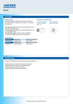
Specific feature of our rectangular housings Our connectors with rectangular housings have 3 possible cable outlets: A, B or C Multi-contact connectors All of an electrical connection can be assembled: Our contacts are designed to replace those in our connectors with removable contacts. 1 cable connector and 1 panel connector/ or/ 1 cable connector and 1 coupler connector. - Male / female panel connector: fixed part of the connector intended to be attached to a device, a wall, a bay, a mobile or immobile assembly. - Male / female cable connector: mobile part of the connector, normally attached...
Open the catalog to page 6
JAEGER CONNECTEURS Connectors with non-removable contacts Technical guides Accessories Connectors with removable contacts Connectors with non-removable contacts Standard Series / Standard Thermocouple Series / Rapid Series / Weatherproof Series / Hermetic Series
Open the catalog to page 7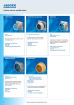
Connectors with non-removable contacts Standard Series Standard Thermocouple Series Rapid Series Standard Standard High Voltage Standard with Thermocouple contacts Rapid Rapid with gold-plated contacts Rapid High Voltage Our Standard Series is particularly versatile. It is a sound value, simple yet robust. • Multi-pole with 3 to 52 solder contacts • Screw locking • IP 50 – 54 • Rectangular housing with 3 possible cable outlets Our Thermocouple Series is particularly suitable for applications requiring temperature measurements. • Multi-pole with 3 solder contacts • Screw locking • IP 50 – 54 •...
Open the catalog to page 8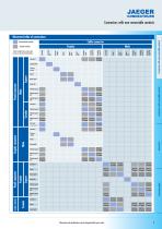
illustrated table of connections Recommended assembly ^Possible assembly *All the assemblies shown can be created, but some are not always the ideal solution. JAEGER CONNECTEURS Connectors with non-removable contacts Cable connector Standard Standard HV Thermocouple Rapid Rapid gold Rapid HV Weatherproof Weatherproof HP Weatherproof PG Standard Weatherproof Weatherproof HP Weatherproof from 3 to PG 17 contacts Hermetic (except Push-Pull) Standard Thermocouple Rapid Rapid gold Weatherproof Weatherproof HP Rapid Rapid gold Weatherproof Weatherproof HP Weatherproof PG Standard Rapid Rapid gold from...
Open the catalog to page 9
Panel connector Circular male panel connectors housings 1 and 2 Circular male panel connectors housings 3 to 5 Cable connector Coupler connector Cable connector - Panel connector assembly Assembly Square female panel connector Male cable conneOor - Female coupler connector * B: minimum disconnection distance Dimensions and specifications may be changed without prior notice
Open the catalog to page 10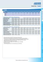
Part Number Housing Male panel connectors - Female cable connectors - Male coupler connectors - For the version with 4 contacts 0 4 mm, contact No. 4 of the panel connector and the coupler connector, which makes the electrical connection before the other 3 contacts and disconnects it after separation, can be used as a ground contact. - ° The panel connectors are also compatible with the Weatherproof cable connectors page 22 and Weatherproof PG cable connectors page 26. - ” Square female panel connectors and female coupler connectors are also of the „Rapid" type, page 16 with 3 to 12 contacts....
Open the catalog to page 11
B: minimum disconnection distance 12 Dimensions and specifications may be changed without prior notice
Open the catalog to page 12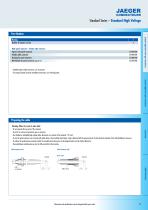
Male panel connector - Female cable connector Square male panel connector 536 893 006 Female cable connector 532 893 006 Housing for panel connector 536 886 006 Flat-Gasket for panel connector (pack of 10) 536 945 006 - Sealable tamper-evident connectors, see: Accessories. - For wiring and panel connector installation instructions, see: Technical guides. Preparing the cable Warning: When the circuit is under load: - Do not separate the two parts of the connector - Do not fit or remove the protective caps on connectors - Use shielded or unshielded high-voltage cables. Maximum cross-section of...
Open the catalog to page 13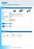
Thermocouple Series – Standard with Thermocouple contacts Technical Data Panel connector Panel connector, cable connector and coupler connector Locking Protection Contacts Max. current Contact resistance between pin and socket Breakdown voltage between adjacent pins Breakdown voltage between peripheral pins contact and ground Insulation resistance Operating temperature Materials Max. cross-section of soldered conductors Thermocouple Identification of contacts Polarity Number iron + 1 constantan 2 chromel + 1 alumel 2 copper + 1 constantan 2 Cable connector Coupler connector rectangular housing...
Open the catalog to page 14All HUMMEL catalogs and technical brochures
 Cable Glands Main Catalogue
236 Pages
 HSK-K-Flex
2 Pages
 HSK-K-PVDF
2 Pages
 HSK-K-FLAKA
2 Pages
 HSK-K-MULTI
2 Pages
 HSK-K
HSK-K2 Pages
 VariaPro Product range
8 Pages
 TWINTUS
6 Pages
 HSK-K-Ex Active
6 Pages
 HSK-INOX Hygienic Design
6 Pages
 VariaPro Rail
4 Pages
 Hybrid Solutions
6 Pages
 M23 Connectors
6 Pages
 M40 Circular Connectors
4 Pages
 M12 Power
28 Pages


Archived catalogs
 Product range Cable Glands
6 Pages
 Circular Connectors Main Catalogue
200 Pages
 Cable Protection Systems
36 Pages


- Hydraulic fitting
- Screw-in fitting
- HUMMEL data connector
- Pneumatic fitting
- HUMMEL electrical power supply connector
- Metal fitting
- HUMMEL metal connector
- Stainless fitting
- Threaded fitting
- HUMMEL brass fitting
- Elbow fitting
- HUMMEL screw-in connector
- HUMMEL industrial connector
- Cable sleeve
- HUMMEL IP67 connector
- Rectangular connector