- Catalogs
- HUBA CONTROL
- OEM Pressure sensor 503 0 ... 2.5 - 25 bar
- Company
- Products
- Catalogs
- News & Trends
- Exhibitions
OEM Pressure sensor 503 0 ... 2.5 - 25 bar
1 /5Pages

OEM Pressure sensor 503 0 ... 2.5 - 25 bar
1 /5Pages
Catalog excerpts
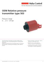
FOR FINE PRESSURE AND FLOW MEASUREMENT Partial automatic production, giving ideal price / performance ratio. Ideal for use as a control element, owing as a result of a small hysteresis Incorporates all the benefits of ceramics technology for industrial applications Type 503 pressure transmitters, with their excellent price / performance ratio, are specially designed for industrial OEM applications. Partially automated production techniques allow us to produce high quantities, yet retaining the flexibility to offer different versions. Huba Control type 503 - Technical data subject to change - Edition 05/2018 1/5
Open the catalog to page 1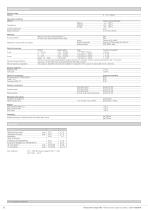
Pressure range_ Operating conditions Medium Overload admissible Rupture pressure _Liquids and neutral gases Medium_+2 ... +90 °C_ ABS for cover with connector RAST 2.5 ousing materia PA 6 for cover with connector DIN or cable Materials in contact with the medium Pressure connector_Grivory GV 5H or Noryl GTX 20% GF Sealing materialFPM, EPDM, NBR Electrical overview Polarity reversal protection Electromagnetic compatibility Output Power supply Load Current consumption Short circuit proof and protected against polarity reversal. For connector versions mechanical protection only. The correct wiring...
Open the catalog to page 2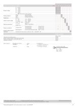
Accessories (supplied loose) Order numberl Order number Safety spring for plug connector_105883 Female connector DIN EN 175301-803-A with sealing_103510 Female connector RAST 2.5 with cable 1450 mm_103167 AMP connector 4)_Manufacturer's Part No._Colour Connector with cable 1 Other pressure ranges on request 2) According to ISO standard R 1629, other sealing materials on request 3) Delivery without female connector 4) To be ordered separately from original manufacturer. Further information can be found in the manufacturer specification No. 114-18049 Huba Control type 503 - Technical data subject...
Open the catalog to page 3
brown white green 0UT-@= 4/5 Huba Control type 503 - Technical data subject to change - Edition 05/2018
Open the catalog to page 4
Huba Control SA Succursale France Rue Lavoisier Technopole Forbach-Sud 57602 Forbach Cedex Telephone +33 (0) 387 847 300 Telecopieur +33 (0) 387 847 301 [email protected] Huba Control AG Branch Office United Kingdom Unit 13 Berkshire House County Park Business Centre Shrivenham Road Swindon Wiltshire SN1 2NR Phone +44 (0) 1993 776667 Fax +44 (0) 1993 776671 [email protected] 5/5 Huba Control type 503 - Technical data subject to change - Edition 05/2018
Open the catalog to page 5All HUBA CONTROL catalogs and technical brochures
 Pressure sensor 515
6 Pages
 506 Pressure sensor
5 Pages
 PRODUCT OVERVIEW
23 Pages
 410 Force cell
3 Pages
 OEM Flowsensor for Liquids
8 Pages


- Flowmeter
- Display module
- Volume flow monitor
- Liquid flow monitor
- Force sensor
- LCD display panel
- Tension/compression force transducer
- Analog pressure transmitter
- Pressure switch
- Pressure probe
- Precision flow meter
- Membrane pressure transmitter
- Waterproof pressure transmitter
- Stainless steel pressure transmitter
- Relative pressure transmitter
- In-line flow meter
- Beam type force sensor
- Mechanical pressure switch
- Digital pressure transmitter