Group: Graco

Catalog excerpts
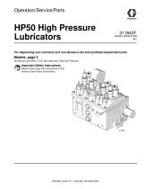
HP50 High Pressure Lubricators For dispensing non-corrosive and non-abrasive oils and synthetic-based lubricants. 50,000 psi (344 MPa, 3,447 bar) Maximum Working Pressure Important Safety Instructions Read all warnings and instructions in this manual. Save these instructions. PROVEN QUALITY. LEADING TECHNOLOGY
Open the catalog to page 1
t Models with this symbol are CE and ATEX certified
Open the catalog to page 2
Warnings The following warnings are for the setup, use, grounding, maintenance, and repair of this equipment. The exclamation point symbol alerts you to a general warning and the hazard symbol refers to procedure-specific risk. Refer back to these warnings. Additional, product-specific warnings may be found throughout the body of this manual where applicable.
Open the catalog to page 3
Drive Mechanism NOTICE All installation, maintenance, and repair work must be completed by qualified personnel. A 1-1/4 inch diameter shaft is provided to connect the lubricator to a rotary power source. A woodruff key and key way on the shaft are provided to aid in connecting this source. Install protective guards around all drive components. The equipment must be grounded to reduce the risk of static sparking. Static sparking can cause fumes to ignite or explode. Grounding provides and escape wire for the electric current. NOTICE The recommended speed of the box lubricator drive shaft is...
Open the catalog to page 5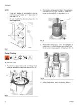
Three sight glasses (B) are provided in the reservoir at various levels to permit observation of fluid level (FIG. 3). 2. Remove the vent plug (A) on top of the sight glass and fill the housing sight well with oil to 3/8-inch below the discharge of the drip tube (FIG. 5). Oil level should not be allowed to drop below the bottom sight glass. 3. Replace the vent plug (A). Check the sight glass to insure that it is properly seated against the o-ring (D) to prevent air leakage into the sight well (FIG. 6). Pump Priming To prime the pump: 1. Turn the feed adjustment nut (C) on indicator stem as...
Open the catalog to page 6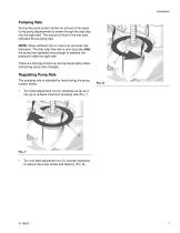
Pumping Rate During the pump suction stroke an amount of oil equal to the pump displacement is drawn through the drip tube into the sight well. The amount of fluid in the site tube indicates the pumping rate. NOTE: Allow sufficient time to insure an accurate rate indication. The drip tube flow rate is only accurate after the pump has operated long enough to stabilize the pressure inside the sight well. C There is a time lag at start-up, during low pumping rates, and during pump rate changes. Regulating Pump Rate The pumping rate is adjusted by hand during the pump suction stroke. • Turn...
Open the catalog to page 7
Service Pressure Relief Procedure Service Instructions 1. Check lubricator operation by observing the drip tube. If the sight glass well pumps dry or no flow is observed, check the following points until the cause is determined and corrected. The equipment stays pressurized until pressure is relieved. To reduce the risk of serious injury from pressurized fluid, accidental spray from the dispenser, or splashing fluid, follow this Pressure Relief Procedure whenever you: • Check the vent plug (A) for proper sealing. Any knicks or cracks in the rubber plug will cause an air leak into the sight...
Open the catalog to page 8
2. If items listed in step 1 are not the cause, check the pump assembly. The following items should be checked before removing the pump assembly from the cover. • • Keep a spare pump on hand for use during emergencies and when the pump is being repaired. • If a spare pump is available, it will not be necessary to stop the equipment the lubricator is installed on or to empty the reservoir. Check the sight glass for inward leakage due to a crack in the sight glass, improper sight glass seating, or a defective o-ring. Repair as required (FIG. 6, page 6). Check for an obstruction in the drip...
Open the catalog to page 9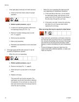
If the sight glass continues to fill with lubricant: a. Check all terminal check valves for proper operation. a. If the level falls to less than 1/4 inch above the sight glass flange, add lubricant to the proper level (3/8 inch below the discharge of the drip tube) through the vent hole. b. If the level is too high, remove the vent plug and allow the unit to pump down before replacing the vent plug. b. Relieve system pressure, page 8. c. If valves are operating properly, disconnect the discharge tubing (E) (FIG. 10) When the unit is operating the sight level will vary depending on...
Open the catalog to page 10
High Pressure Lubricator Parts High Pressure Lubricator Parts 46
Open the catalog to page 11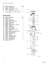
High Pressure Lubricator Parts Pump Parts
Open the catalog to page 12
High Pressure Lubricator Parts Check Valve Parts Drawing and Parts List *Supplied with Discharge Check Valve 564335 only. Not supplied with Terminal Check Valves. 564336 Terminal Check Valve 564335 Discharge Check Valve - 3/8” OD Tube Steam Heater Parts Drawing and Parts List ELBOW, 1/4 NPT Steam Pipe 2 SEAL PLUG, Steam Pipe 2 SEAL, Steam Pipe 2
Open the catalog to page 13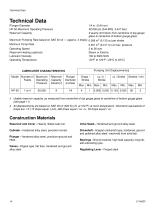
Technical Data Technical Data Plunger Diameter HP-50 Maximum Operating Pressure Reservoir Capacity Maximum Pumping Rate based on SAE 40 oil — (approx. Minimum Pump Rate Operating Speed Reservoir Heating (optional) Lubricant Viscosity Operating Temperature 1/4 in. (0.64 cm) 50,000 psi (344 MPa, 3,447 bar) 9 quarts (8.5 liters) from centerline of top gauge glass to centerline of bottom gauge glass 4 drops) 0.008 in3 (0.133 cc) per stroke 0.001 in3 (0.017 cc) at max. pressure 3 to 36 rpm Steam or Electric 100 to 5000 SUS -20°F to 120°F (-29°C to 49°C) t Usable reservoir capacity, as measured...
Open the catalog to page 14
Graco Standard Warranty Graco warrants all equipment referenced in this document which is manufactured by Graco and bearing its name to be free from defects in material and workmanship on the date of sale to the original purchaser for use. With the exception of any special, extended, or limited warranty published by Graco, Graco will, for a period of twelve months from the date of sale, repair or replace any part of the equipment determined by Graco to be defective. This warranty applies only when the equipment is installed, operated and maintained in accordance with Graco’s written...
Open the catalog to page 16All GRACO catalogs and technical brochures
-
 Pro Xp® Electrostatic Spray Guns
12 Pages
-
 Supply Pumps
8 Pages
-
 XP™ and XM Series Sprayers
28 Pages
-
 Triton™
8 Pages
-
 Fusion® CS
6 Pages
-
 AA G40 Automatic
4 Pages
-
 ToughTek® Mortar Equipment
22 Pages
-
 FRP Systems
16 Pages
-
 SaniSpray HP™
20 Pages
-
 PFP Sprayers
8 Pages
-
 Hoses, Guns and Accessories
24 Pages
-
 Automatic Lubrication Equipment
158 Pages
-
 Petroleum Handling Equipment
3 Pages
-
 AutoPlus™Valve
2 Pages
-
 Reactor
20 Pages
-
 FUSION™
24 Pages
-
 T-MAX™
3 Pages
-
 SDV15
SDV1512 Pages
-
 Air-Lube Spra-Control Valve
1 Pages
-
 GL-11 Grease Injectors
2 Pages
-
 GL-1 Series Grease Injectors
6 Pages
-
 G3 Max
4 Pages
-
 G1 Standard
26 Pages
-
 SDSLBFENEU-A, Lubri-Film
7 Pages
-
 SDSGBLENEU-A, Box Lubricant
7 Pages
-
 SDSHUGENEU-A Husky Grease
9 Pages
-
 G1 Plus
34 Pages
-
 E-Series Pneumatic Pumps
2 Pages
-
 Manzel Model 25 Lubricator
14 Pages
-
 Manzel MBL Box Lubricator
18 Pages
-
 Air/Oil AO Series Valves
8 Pages
-
 M2K
M2K3 Pages
-
 Meter-Flo Pumps
4 Pages
-
 E-Series Lube Packages
2 Pages
-
 Manzel HP Lubricator
2 Pages
-
 Manzel® Model 25 Lubricator
8 Pages
-
 Force Feed Box Lubricators
16 Pages
-
 Manzel GBL 7500
2 Pages
-
 Manzel® DSL Lubricators
4 Pages
-
 Balancing Valve
2 Pages
-
 Dyna-Star 10:1
4 Pages
-
 GLC 4400 Multi-Purpose
2 Pages
-
 GLC 2200 Controller
2 Pages
-
 G3 Electric Lubrication Pump
8 Pages
-
 G1 Series Lubrication Pumps
8 Pages
-
 High Speed Spindl-Gard
4 Pages
-
 InvisiPac
8 Pages
-
 SaniForce Equipment Catalog
32 Pages
-
 Fine Finish Sprayers Brochure
13 Pages
-
 Graco ILE Buyer's Guide
136 Pages
-
 AirPro Brochure
12 Pages
-
 Electric Sprayers Brochure
24 Pages
-
 RS Resin Spray Guns
8 Pages


Archived catalogs
-
 High-Flo
2 Pages
-
 Triton 3D
2 Pages
-
 Reactor IP
8 Pages
-
 Gelcoat
8 Pages
-
 E-Flo
E-Flo2 Pages
-
 Chopper
8 Pages
-
 Style your process
2 Pages
-
 PD44 Dispensing System
8 Pages
-
 PCF Metering System
8 Pages
-
 PR70
PR7012 Pages
-
 MD2 Dispense Valve
2 Pages
-
 XTREME-DUTY™
2 Pages
-
 XM Plural-Component Sprayers
8 Pages
-
 Reactor®
12 Pages
-
 Process Equipment
12 Pages
-
 Graco’s new Hydra-CleanTM
2 Pages
-
 Fusion®
16 Pages
-
 Xtreme® Airless Sprayers
3 Pages
-
 Wood Finishing
140 Pages
-
 Paint finishing spray packages
16 Pages


