Group: Graco

Catalog excerpts

Feed Direct Rotary Suction fed box lubricator for dispensing mineral oil-based or synthetic lubricants. For ©Important Safety Instructions Read all warnings and instructions in this manual. Save these instructions. See page 2 for model information PROVEN QUALITY. LEADING TECHNOLOGY.
Open the catalog to page 1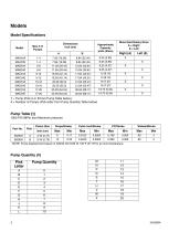
Models Model Specifications Dimensions inch (cm) A MAA†#A MAA†#E MAB†#A MAB†#E MAC†#A MAC†#E MAD†#A MAD†#E MAE†#A MAE†#E Approximate Capacity pints (liters) Direct End Rotary Drive A = Right E = Left † = Pump (Pick A or B from Pump Table below). # = Number of Pumps (Pick letter from Pump Quantity Table below) Pump Table (†) 1000 PSI (MPa/ bar) Maximum pressure Piston Size inch (cm) Cubic Inch/Stroke Pump Quantity (#) Pick Letter A B C D E F G H J K L
Open the catalog to page 2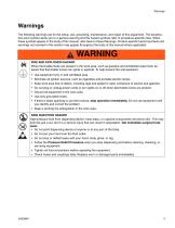
Warnings The following warnings are for the setup, use, grounding, maintenance, and repair of this equipment. The exclamation point symbol alerts you to a general warning and the hazard symbols refer to procedure-specific risks. When these symbols appear in the body of this manual, refer back to these Warnings. Product-specific hazard symbols and warnings not covered in this section may appear throughout the body of this manual where applicable. WARNING FIRE AND EXPLOSION HAZARD When flammable fluids are present in the work area, such as gasoline and windshield wiper fluid, be aware that...
Open the catalog to page 3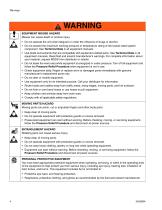
WARNING EQUIPMENT MISUSE HAZARD Misuse can cause death or serious injury. • Do not operate the unit when fatigued or under the influence of drugs or alcohol. • Do not exceed the maximum working pressure or temperature rating of the lowest rated system component. See Technical Data in all equipment manuals. • Use fluids and solvents that are compatible with equipment wetted parts. See Technical Data in all equipment manuals. Read fluid and solvent manufacturer’s warnings. For complete information about your material, request MSDS from distributor or retailer. • Do not leave the work area...
Open the catalog to page 4
Installation Component Identification B C J K F Sight feed cover Drip tube Feed regulator Pump mounting screws Metering plunger Pump crosshead Inlet tube Inlet strainer Sight chamber well Discharge plunger (shown at top of stroke) Reservoir Hand Crank Fill cover Drive shaft Sight glass
Open the catalog to page 5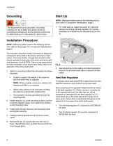
Start Up NOTE: Reference letters used in the following instructions refer to Component Identification, page 5. The equipment must be grounded. Grounding reduces the risk of static and electric shock by providing an escape wire for the electrical current due to static build up or in the event of a short circuit. 1. For initial start-up, adjust the pump for maximum delivery by turning the feed regulator (C) counterclockwise as indicated by the directional arrow (FIG. 2). Installation Procedure NOTE: Reference letters used in the following instructions refer to Parts page 10 or Component...
Open the catalog to page 6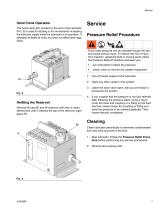
Hand Crank Operation The hand crank (M), located on the end of the lubricator (FIG. 3) is used for starting or for momentarily increasing the lubricant supply while the lubricator is in operation. It operates all feeds at once, but does not affect feed regulation. Pressure Relief Procedure Fluid under pressure can be injected through the skin and cause serious injury. To reduce the risk of injury from injection, splashing fluid or moving parts, follow the Pressure Relief Procedure whenever you: • are instructed to relieve the pressure, check, clean or service any system equipment, 1. Turn...
Open the catalog to page 7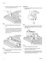
a. Remove the discharge line connection and the pump mounting screws (D) (FIG. 5). Reassembly 1. Before replacing pump, position yoke down as far as possible (FIG. 7). Loosen the adjacent pump mounting screws (D). Lift out front end of pump (end with feed regulator screw), pulling it forward and upward at the same time. This will allow the yoke or crosshead to clear the drive shaft and the pump can be lifted out (FIG. 6). 2. Install pump by inserting the back end of the pump (end without the feed regulator screw) in the reservoir first (FIG. 8). FIG. 8 3. Connect discharge line to pump...
Open the catalog to page 8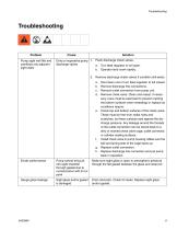
Problem Pump sight well fills and overflows into adjacent sight wells Dirty or inoperative pump 1. Flush discharge check valves. discharge valves a. Turn feed regulator to full open. b. Operate hand crank rapidly. 2. Remove discharge check valves if condition still exists. a. b. c. d. Shut down unit or turn feed regulator to full closed. Remove discharge line connections. Remove outlet connection from pump unit. Remove check valve. Clean and reseat, if necessary, (care must be exercised to prevent marking the bottom surfaces when reseating) or replace as conditions require. e. Check top and...
Open the catalog to page 9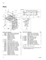
12 557391 PLUG, dry seal, 1/4 nptf 1 556692 SIGHT GLASS (6 feed) (9-12 pumps) 2 556694 SIGHT GLASS (8 feed) (13-16 pumps) 2 556692 SIGHT GLASS (6 feed) (17-20 pumps) 2 556694 SIGHT GLASS (8 feed) (17-20 pumps) 1 556725 GASKET, sight, 8 FD (5-8 pumps) 1 556724 GASKET, sight, 6 FD (9-12 pumps) 2 556725 GASKET, sight, 8 FD (13-16 pumps) 2 556724 GASKET, sight, 6 FD (17-20 pumps) 2 556725 GASKET, sight, 8 FD (17-20 pumps) 1 PLATE, sight glass RIGHT SIDE direct drive rotary LEFT SIDE direct drive rotary LABEL, name, serial number LABEL, identification PLATE, sight glass (1-4 pumps) PLATE, sight...
Open the catalog to page 10
31 - Blank Plate Quantity Based on Number of Pumps (Code column relates to Pump Quantity, see page 2)
Open the catalog to page 11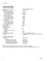
Technical Data Technical Data Maximum operating pressure◆ Drive Speed Number of drops per stroke◆ 5/16 inch model: maximum 5/16 inch model: minimum 3/16 inch model: maximum 3/16 inch model: minimum Cubic inch per stroke◆ 5/16 inch model: maximum 5/16 inch model: minimum 3/16 inch model: maximum 3/16 inch model: minimum CC per stroke◆ 5/16 inch model: maximum 5/16 inch model: minimum 3/16 inch model: maximum 3/16 inch model: minimum Drops per pint◆ Drops per cubic inch◆ Drops per cc◆ Strokes per minute◆ maximum minimum Viscosity*: SSU @ 100°F (37.78°C) maximum minimum Operating Temperature...
Open the catalog to page 12All GRACO catalogs and technical brochures
-
 Pro Xp® Electrostatic Spray Guns
12 Pages
-
 Supply Pumps
8 Pages
-
 XP™ and XM Series Sprayers
28 Pages
-
 Triton™
8 Pages
-
 Fusion® CS
6 Pages
-
 AA G40 Automatic
4 Pages
-
 ToughTek® Mortar Equipment
22 Pages
-
 FRP Systems
16 Pages
-
 SaniSpray HP™
20 Pages
-
 PFP Sprayers
8 Pages
-
 Hoses, Guns and Accessories
24 Pages
-
 Automatic Lubrication Equipment
158 Pages
-
 Petroleum Handling Equipment
3 Pages
-
 AutoPlus™Valve
2 Pages
-
 Reactor
20 Pages
-
 FUSION™
24 Pages
-
 T-MAX™
3 Pages
-
 SDV15
SDV1512 Pages
-
 Air-Lube Spra-Control Valve
1 Pages
-
 GL-11 Grease Injectors
2 Pages
-
 GL-1 Series Grease Injectors
6 Pages
-
 G3 Max
4 Pages
-
 G1 Standard
26 Pages
-
 SDSLBFENEU-A, Lubri-Film
7 Pages
-
 SDSGBLENEU-A, Box Lubricant
7 Pages
-
 SDSHUGENEU-A Husky Grease
9 Pages
-
 G1 Plus
34 Pages
-
 E-Series Pneumatic Pumps
2 Pages
-
 Manzel MBL Box Lubricator
18 Pages
-
 Air/Oil AO Series Valves
8 Pages
-
 M2K
M2K3 Pages
-
 Meter-Flo Pumps
4 Pages
-
 E-Series Lube Packages
2 Pages
-
 Manzel HP Lubricator
2 Pages
-
 Manzel® Model 25 Lubricator
8 Pages
-
 Force Feed Box Lubricators
16 Pages
-
 Manzel GBL 7500
2 Pages
-
 Manzel® DSL Lubricators
4 Pages
-
 Balancing Valve
2 Pages
-
 Dyna-Star 10:1
4 Pages
-
 GLC 4400 Multi-Purpose
2 Pages
-
 GLC 2200 Controller
2 Pages
-
 G3 Electric Lubrication Pump
8 Pages
-
 G1 Series Lubrication Pumps
8 Pages
-
 High Speed Spindl-Gard
4 Pages
-
 InvisiPac
8 Pages
-
 SaniForce Equipment Catalog
32 Pages
-
 Fine Finish Sprayers Brochure
13 Pages
-
 Graco ILE Buyer's Guide
136 Pages
-
 AirPro Brochure
12 Pages
-
 Electric Sprayers Brochure
24 Pages
-
 RS Resin Spray Guns
8 Pages


Archived catalogs
-
 High-Flo
2 Pages
-
 Triton 3D
2 Pages
-
 Reactor IP
8 Pages
-
 Gelcoat
8 Pages
-
 E-Flo
E-Flo2 Pages
-
 Chopper
8 Pages
-
 Style your process
2 Pages
-
 PD44 Dispensing System
8 Pages
-
 PCF Metering System
8 Pages
-
 PR70
PR7012 Pages
-
 MD2 Dispense Valve
2 Pages
-
 XTREME-DUTY™
2 Pages
-
 XM Plural-Component Sprayers
8 Pages
-
 Reactor®
12 Pages
-
 Process Equipment
12 Pages
-
 Graco’s new Hydra-CleanTM
2 Pages
-
 Fusion®
16 Pages
-
 Xtreme® Airless Sprayers
3 Pages
-
 Wood Finishing
140 Pages
-
 Paint finishing spray packages
16 Pages


