 Website:
GRACO
Group: Graco
Catalog excerpts

For Single-Line Parallel Automatic Lubrication Systems. Important Safety Instructions Read all warnings and instructions in this manual and related automatic lubrication system instruction manuals. Save all instructions. Fluid from the injector, leaks, or ruptured components can inject fluid into your body and cause extremely serious injury, including the need for amputation. Fluid injected into the skin might look like just a cut, but it is a serious injury. Get immediate surgical treatment. Fluid splashed in the eyes or on the skin can also cause serious injury. The equipment may be pressurized already, or it could become pressurized by an automatic lube cycle initiated by Lubrication Controller (timer). Disconnect power to the timer, and disconnect the air supply to the pump module to ensure that the system is depressurized. See the pressure relief procedure in the pump manual incuded with your automatic lubrication system. GL-1 Injector Models Part No. 114901 114902 114903 114904 114905 117206 114909 Description Injector, GL-1, one point Injector, GL-1, two point Injector, GL-1, three point Injector, GL-1, four point Injector, GL-1, five point Injector, GL-1, six point Injector, GL-1, replacement PROVEN QUALITY. LEADING TECHNOLOGY
Open the catalog to page 1
Installation Instructions Reference letters used in the following instructions, refer to FIG. 2. 2. Install injectors on a flat, hard surface using mounting brackets (a). Group injectors to minimize feed line length. 3. Connect fluid supply line (c) to injectors. Install injectors in locations that allow easy and safe servicing access. Install injectors in areas that minimize accidental injector damage by moving equipment. Injector outputs can be combined for a common bearing point with a large grease requirement but the output for a single injector cannot be split into multiple bearing...
Open the catalog to page 2
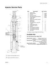
Injector Service Parts Injector Service Parts Qty 1 1 1 1 1 1 1 1 2 1 1 1 1 1 1 1 1 Item Description 5 Zerk fitting and cap assembly 6 Copper gasket (used on all manifold models) 8 Indicator pin ★ Included in Injector Repair Kit 241234 only (See Kit 241234 parts in Injector Service Parts list.) Torque to 50-55 ft-lbs (68-74.5 N.m) ^ Torque to 35-40 ft-lbs (47-54 N.m)
Open the catalog to page 3
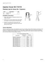
Installation Instructions 1. Apply a light coating of transparent lubricant to the inside of cap (21). 2. Slide cap (21) over the indicator stem of the injector far enough to cover the groove in the piston plug. 3. Slide the o-ring (22) down over the cap to the groove in the piston plug, forcing the cover into the groove to form a seal. Volume Adjustment *Maximum adjustment setting is when adjusting screw (2) is just making contact with the indicator pin (8) with no inlet pressure. Turn adjusting screw clockwise (in), to reduce output. To adjust, loosen lock nut (3) and turn adjusting screw...
Open the catalog to page 4
Technical Data Maximum operating pressure . . . . . . . . . . . . . . . . . . . . . . . . . . Suggested operating pressure . . . . . . . . . . . . . . . . . . . . . . . . . Reset pressure . . . . . . . . . . . . . . . . . . . . . . . . . . . . . . . . . . . . . Output volume per cycle . . . . . . . . . . . . . . . . . . . . . . . . . . . . . Wetted parts . . . . . . . . . . . . . . . . . . . . . . . . . . . . . . . . . . . . . . . carbon steel, stainless steel, copper, fluoroelastomer Recommended fluids . . . . . . . . . . . . . . . . . . . . . . . . . . . . . . . . N.L.G.I. #2 grease down...
Open the catalog to page 5
Graco Standard Warranty Graco warrants all equipment referenced in this document which is manufactured by Graco and bearing its name to be free from defects in material and workmanship on the date of sale to the original purchaser for use. With the exception of any special, extended, or limited warranty published by Graco, Graco will, for a period of twelve months from the date of sale, repair or replace any part of the equipment determined by Graco to be defective. This warranty applies only when the equipment is installed, operated and maintained in accordance with Graco’s written...
Open the catalog to page 6All GRACO catalogs and technical brochures
-
Pro Xp® Electrostatic Spray Guns
12 Pages
-
Supply Pumps
8 Pages
-
XP™ and XM Series Sprayers
28 Pages
-
Triton™
8 Pages
-
Fusion® CS
6 Pages
-
AA G40 Automatic
4 Pages
-
ToughTek® Mortar Equipment
22 Pages
-
FRP Systems
16 Pages
-
SaniSpray HP™
20 Pages
-
PFP Sprayers
8 Pages
-
Hoses, Guns and Accessories
24 Pages
-
Automatic Lubrication Equipment
158 Pages
-
Petroleum Handling Equipment
3 Pages
-
AutoPlus™Valve
2 Pages
-
Reactor
20 Pages
-
FUSION™
24 Pages
-
T-MAX™
3 Pages
-
SDV15
12 Pages
-
Air-Lube Spra-Control Valve
1 Pages
-
GL-11 Grease Injectors
2 Pages
-
G3 Max
4 Pages
-
G1 Standard
26 Pages
-
SDSLBFENEU-A, Lubri-Film
7 Pages
-
SDSGBLENEU-A, Box Lubricant
7 Pages
-
SDSHUGENEU-A Husky Grease
9 Pages
-
G1 Plus
34 Pages
-
E-Series Pneumatic Pumps
2 Pages
-
Manzel Model 25 Lubricator
14 Pages
-
Manzel MBL Box Lubricator
18 Pages
-
Air/Oil AO Series Valves
8 Pages
-
M2K
3 Pages
-
Meter-Flo Pumps
4 Pages
-
E-Series Lube Packages
2 Pages
-
Manzel HP Lubricator
2 Pages
-
Manzel® Model 25 Lubricator
8 Pages
-
Force Feed Box Lubricators
16 Pages
-
Manzel GBL 7500
2 Pages
-
Manzel® DSL Lubricators
4 Pages
-
Balancing Valve
2 Pages
-
Dyna-Star 10:1
4 Pages
-
GLC 4400 Multi-Purpose
2 Pages
-
GLC 2200 Controller
2 Pages
-
G3 Electric Lubrication Pump
8 Pages
-
G1 Series Lubrication Pumps
8 Pages
-
High Speed Spindl-Gard
4 Pages
-
InvisiPac
8 Pages
-
SaniForce Equipment Catalog
32 Pages
-
Fine Finish Sprayers Brochure
13 Pages
-
Graco ILE Buyer's Guide
136 Pages
-
AirPro Brochure
12 Pages
-
Electric Sprayers Brochure
24 Pages
-
RS Resin Spray Guns
8 Pages
Archived catalogs
-
High-Flo
2 Pages
-
Triton 3D
2 Pages
-
Reactor IP
8 Pages
-
Gelcoat
8 Pages
-
E-Flo
2 Pages
-
Chopper
8 Pages
-
Style your process
2 Pages
-
PD44 Dispensing System
8 Pages
-
PCF Metering System
8 Pages
-
PR70
12 Pages
-
MD2 Dispense Valve
2 Pages
-
XTREME-DUTY™
2 Pages
-
XM Plural-Component Sprayers
8 Pages
-
Reactor®
12 Pages
-
Process Equipment
12 Pages
-
Graco’s new Hydra-CleanTM
2 Pages
-
Fusion®
16 Pages
-
Xtreme® Airless Sprayers
3 Pages
-
Wood Finishing
140 Pages
-
Paint finishing spray packages
16 Pages


