
Catalog excerpts
Instruction Manual
Open the catalog to page 1
provides the right solution for all your control needs! Providing excellent performance and functionality, Genie-NX performs simple logic, timing, counting, and real time clock operations. It is an ideal programmable controller for simple control applications such as building construction equipments, HVAC, parking lot lighting and other applications in which cost is a primary design issue. All programming and data adjustments can be done via the on-board keypad and display or with the help of a software. Programming Genie-NX with the help of G-Soft NX configuration software is quite simple,...
Open the catalog to page 2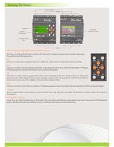
The 8 keys located on the front facia of Genie-NX are used to configure, program and control the application. They perform the following actions: FRONT VIEW OF KEYPAD & FUNCTIONS OF KEYS This key is used to delete a program element or a blank line, if the cursor is located at the extreme column. DEL This key is used for selecting/exiting a parameter in the edit mode and to show either the Parameters or Program while the program is running. This feature is also useful for debugging. ALT On the program editor screen, the arrow keys are used to move up, left, down and right. The position on...
Open the catalog to page 3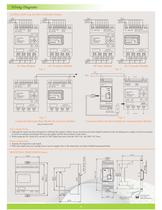
Wiring Diagrams SUPPLY FUSE +- Q1 Q2 Q3 Q4 LOAD LOAD LOAD LOAD OUTPUT 4 X RELAY / 8A SUPPLY FUSE PROGRAM RUN PARAMETER UTILITIES Z1 Z3 Z2 OK Q2 DEL Z4 ALT INPUT 8XAC ESC Q1 Q3 Q4 LOAD LOAD LOAD LOAD SUPPLY FUSE L N OUTPUT 4 X RELAY / 8A L N I1 I2 I3 I4 I5 I6 I7 I8 C1 C2 110 - 230 V AC 50 / 60 Hz SUPPLY FUSE L N L N I1 I2 I3 I4 I5 I6 I7 I8 C1 C2 110 - 230 V AC 50 / 60 Hz INPUT 8XAC OUTPUT 4 X RELAY / 8A SUPPLY FUSE +- + - I1 I2 I3 I4 I5 I6 ANAN C1 C2 12 - 24V DC INPUT 6XDC An1, An2 = 0-10 V DC SUPPLY FUSE +- OP2 LOAD LOAD LOAD LOAD OUTPUT 4 X RELAY / 8A SUPPLY FUSE - PROGRAM RUN PARAMETER...
Open the catalog to page 4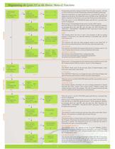
SLV ID 000 BAUD 9600 PARITY NONE STOPBIT 1 CARD > DEVICE DEVICE > CARD DELETE CARD I 1 ------------ Q1 I 2 ------------ T1 EDIT DELETE TRANSFER MODBUS CONF EDIT DELETE TRANSFER MODBUS CONF EDIT DELETE TRANSFER MODBUS CONF EDIT DELETE TRANSFER MODBUS CONF DELETE ! PROGRAM RUN PARAMETER UTILITIES PROGRAM RUN PARAMETER UTILITIES PROGRAM RUN PARAMETER UTILITIES CONTINUE RESET PASSWORD 0000 EXTENSION MODULES A B C BACKLIT CONFIG AUTO DD/MM/YY 01/01/2011 HH:MM 10:40 SET CLOCK PASSWORD EXT MOD BACKLIT CONF SET CLOCK PASSWORD EXT MOD BACKLIT CONF SET CLOCK PASSWORD EXT MOD BACKLIT CONF SET CLOCK...
Open the catalog to page 5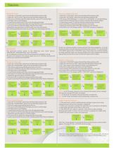
PASSWORD ENABLED Setting the Password 1. Select the “UTILITIES” option from the Main Menu and press OK. 2. Select the “PASSWORD” option from the Sub Menu and press OK. 3. The unlock symbol means that the password is not yet set. 3. The cursor will blink on the first digit of the date, press ALT to edit the digit 4. The digit will now start blinking 5. Using Up(Z4) and Down(Z2) keys select the appropriate digit. 6. Now press Z3 to edit the other digit and using Up & Down keys select the digit. 7. Repeat the same procedure to set all the 4 digits. 8. Now press OK to confirm the changes that...
Open the catalog to page 7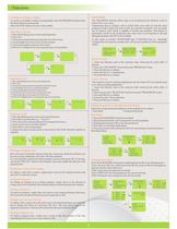
Deleting a Program Line Move the cursor to the first column of the line, if necessary delete the elements one by one to create a blank line. Press Del. The line is deleted. It is also possible to delete the entire program stored in the Genie-NX. To do this, call up the "DELETE" option in the Program menu and validate the deletion of all program lines. Creating or Editing a Ladder Replacing a Link with a Contact To replace a link with a contact, simply place cursor at the required location and press ALT to enter the contact Changing an Element To change an element in an existing program,...
Open the catalog to page 8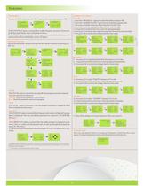
Functions Run Mode Functions If the CONTINUE option is selected then Ladder Program execution will proceed & the Run mode display screen will appear as shown If the RESET option is selected then all special function block parameters are initialized & the Run mode display screen will appear RUN MODE MODBUS SETTINGS To enter into RUN mode select the "Run" option in the main menu and press 'OK'. During the Run mode the user can enter the Run Mode Functions by pressing the ESC key Parameter Lock Slave ID Baud Rate Stop Bits Parity CI ONTINUE RESET I 12345678 SA Q 1234 08:30 ESC PIROGRAM RUN...
Open the catalog to page 9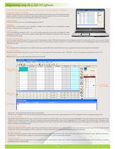
Programming using the G Soft-NX Software G-SOFT NX provides a user-friendly interface wherein the user has to only select contact type and contact number and place it where it is required. Contacts get connected automatically if they are on the same line. User can enter comments for better readability and for future reference . Entering the Program: Select & Place G-SOFT NX allows user to save individual programs on the PC. Saving Programs G-SOFT NX is very powerful in error handling. It displays any possible errors as the program is being entered to make corrections simultaneously....
Open the catalog to page 10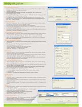
Working with Gsoft-NX To Set Communication Parameters Clock Setting DST (Daylight Saving Time) Setting Transfer Options PC to Device Device to PC Extension Module Selection To Configure Communication Port To Set & Remove Password To Set Backlit Mode 11 Ÿ Select the Configuration >Device Utilities menu command. Then Device Utilities window will pop up as shown in the adjoining window. Ÿ Click on set password. Ÿ Enter four digits password in the two boxes “New password” and “Confirm New” Password then confirm with OK. Ÿ You can delete your assigned password at any time. To do this, enter the...
Open the catalog to page 11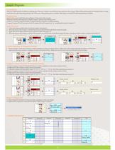
Sample Programs CAR PARKING There are 5 parking spots available in a parking area. There are 2 sensors, one at the entry gate and one at the exit gate. When all the parking spots are occupied, there is a lamp outside the entry gate indicating parking is full. When any of the parking spots is available, other lamp is switched ON indicating parking is available. 5. Select Counter C1 from the I/O selector window and place it in the coil column of line 1. Right click on the counter and select the option counting input. 6. Again select the same counter C1 and place it in the coil column of line3...
Open the catalog to page 13All General Industrial Controls (P) Ltd. catalogs and technical brochures
-
 GIC CATALOGUE 112011
85 Pages