Storage tank level controller
1 /2Pages

Storage tank level controller
1 /2Pages
Catalog excerpts
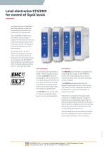
Level electronics ETS/ENR for control of liquid levels Level electronics in combination with float switches or level rod probes permit the control and monitoring of the liquid level. The ETS/ENR level electronics are based on the principle of conductive level measurement and have been developed specifically for process liquids in the general metal finishing industry and for electroplating. The sensitivity can be set in stages according to the conductivity of the process liquid. All level electronics have been tested in accordance with EN 61326 for electromagnetic compatibility and offer functional safety according to SIL 2 in line with EN 61508. Level monitoring Level control For monitoring the liquid level as a MIN or MAX switching contact, The ENR 300 level controller is equipped with a switching relay output for the MIN/MAX the device ETS 100 is used. On exceeding the set maximum level or undershooting the defined minimum level, the contact switches. If the level of the process liquid returns to the “permitted” range, the contact is switched back. control. For monitoring a further minimum or maximum level, there is another switching contact available. The dielectric strength of the signal inputs is 50 V DC. If a higher dielectric strength is required (e.g. in pulseplating processes), the electronic ballast device EVG 200 can be used with an dielectric strength of 200 V DC and has to be connected to each signal inputs of the corresponding level electronics. The level electronics and the electronic ballast device are designed for control cabinets with top-hat rail mounting for close mounting. The ETS 200 device can be used to monitor two separate liquid levels in one tank independently. The ETS 410 level electronics have four separate signal inputs and four relay outputs. This means that four independent levels can be detected in one tank and evaluated, for in-stance via a PLC
Open the catalog to page 1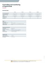
Controlling and monitoring of liquid levels Technical data ETS 100 No. of level switching points Contacts (potential-free) Switching status display Switching voltage Switching current Test function Input Switching delay Output voltage / current Trigger sensitivity 0,05...100 kΩ (10 μS ... 2 x 10⁴ μS) adjustable with 16 stages Dielectric strength Mechanical construction Casing material Flammability class housing Ambient temperature Transport and storage temp.
Open the catalog to page 2All Galvatek catalogs and technical brochures
 control box
2 Pages
 BC and BC/L
2 Pages
 ROTKAPPE ABS
2 Pages
 CALOR heating cartridges
2 Pages
 Rotkappe LC
2 Pages
 Rotkappe BC
2 Pages
 PTFE Rod Heaters GALMAFORM
2 Pages
 Conductive level probe
2 Pages
 Float Switches - MTS
2 Pages
 General Product brochure
8 Pages
 MINIBOX - 2M02
1 Page
 BASE HEATER - 560401
1 Page
 Control-Therm Type T
1 Page
 Control-Therm Type U
1 Page


- Temperature probe
- Resistance temperature sensor
- Level limit switch
- Liquid level detector
- Digital temperature control
- Heat exchanger unit
- Waterproof temperature sensor
- Temperature controller
- Pt100 temperature transducer
- Thermocouple temperature transducer
- Float level switch
- Liquid/liquid heat exchanger
- Stainless steel temperature transducer
- Digital temperature controller
- Stainless steel level detector
- Plate heat exchanger
- Tank level limit switch
- Stainless steel heat exchanger
- Liquid temperature sensor
- Digital thermostat