- Catalogs
- The Fredericks Company
- Principals of operation Electrolytic tilt sensor signal conditioning
Principals of operation Electrolytic tilt sensor signal conditioning
1 /4Pages
Principals of operation Electrolytic tilt sensor signal conditioning
1 /4Pages
Catalog excerpts
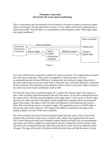
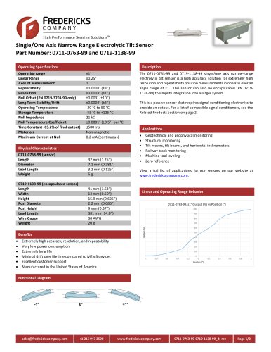
Principals of operation Electrolytic tilt sensor signal conditioning Figure 1 ) is an outline of the basic building block to achieve this result. This flowchart is a representation of the schematic titled Wide angle single axis signal conditionerӔ. This is a description into the operation of an electrolytic tilt sensor to obtain an electrical output relative to tilt angle. The flowchart below ( Figure 1 Micro-controller Output ports Analog to Digital input Fredericks Electrolytic Tilt Sensor Lets start with the micro-controller to define the sensors excitation. Two output ports are used to drive the sensors outer pins. These ports are toggled at a 50 percent duty cycle for a recommended period of around 400 hertz. Assuming that the software to toggle these ports is precisely timed to prevent any deviation from a 50 percent duty cycle there should be a minimum of non-symmetry. Non-symmetry can be defined as direct current to the sensor. Direct current to the sensor can result in poor performance such as drift. Now that the sensor has an excitation signal, letҒs examine the sensors output. This signal is a ratio of the excitation signal determined by the tilt of the sensor. At the null or balanced position the output will be a flat line near the midpoint of the input signal. As the sensor is tilted in either direction, the input waveform will appear with the amplitude increasing with an increasing tilt angle of the sensor. The phase of this waveform will depend on which direction the sensor is tilted. This will indicate positive or negative angles. The signal then goes to a CMOS buffer to prevent any load on the output pin. The output of the buffer is connected to the input of the analog to digital converter in the micro-controller. The micro-controller has the job of processing the signal from the sensor. Since it knows the timing for the excitation to the sensor, it needs to take voltage level samples from the sensor. This is done during each half cycle. Multiple samples during each half cycle are recommended since these can result in a higher bit count and can also be averaged for a more accurate result. One half cycle is subtracted from the other half cycle and the result will be an indication of the tilt angle. The sign of the result will indicate which direction from null that the sensor is tilted. 1 Sensor excitation Sensor output Buffer - CMOS Operational Am Bufferedsignal p lifie r >
Open the catalog to page 1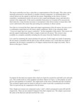
figure 2 below. Universal single dual axis signal conditionerӔ for the remainder of this article. This circuit will provide signal conditioning for either a single or dual axis tilt sensor. This circuit is also available as a complete assembly including the tilt sensor from the Fredericks Company. Lets start by examining the sensor position for each axis. In the single axis mode of operation, the tilt sensor is mounted with the pins in line with the sensitive axis. In the dual axis mode of operation, the tilt sensor is mounted in a 45-degree rotation from the single axis mode. This is shown in...
Open the catalog to page 2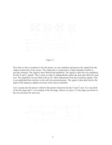
Figure 4 is the input waveform to the a/d converter for each axis. Figure 3 Now that we have excitation to the tilt sensor, we can condition and process the signal from the output (center) pin of the sensor. The output pin is connected to a high impedance buffer to provide isolation. The signal is then filtered and amplified. The signal is split into two amplifiers for the X and Y signals. This is done in order to independently adjust the gain and offset for each axis. The amplifiers are provided with an AC offset adjustment from the excitation signals. This is accomplished thru resistors to...
Open the catalog to page 3
X axis tilt = (X+) (X-) Y axis tilt = (Y+) ֖ (Y-) Now that we have values for the X and Y axis, we can utilize the micro-controller to output this data in various forms. In the reference schematic, the output is delivered in two forms. One is in the form of a pulse width modulated output for each axis. The other is output in serial form to a digital to analog converter. There the output is delivered to two amplifiers for gain and offset adjustment for each axis. The primary software flow to excite and read the tilt sensor and output the sensor data is as follows, 1 - Start an interrupt to toggle...
Open the catalog to page 4All The Fredericks Company catalogs and technical brochures
 Televac br5003
6 Pages
 Televac MP7FR Cold Cathode
2 Pages
 Televac MX4A Convection
2 Pages


Archived catalogs
 2 A Thermocouple Sensor
2 Pages
 Single Axis Narrow Angle
1 Page
 0711-0768-99-0719-1143-99_ds
2 Pages
 Electrolytictilt
4 Pages
 0703-0703-99 TrueTilt
2 Pages


- Communication gateway
- Tilt sensor
- Industrial gateway
- Ethernet gateway
- Serial gateway
- Digital inclination sensor
- 2-axis tilt sensor
- MEMS inclination sensor
- RS-485 gateway
- Signal conditioner
- Multi-axis tilt sensor
- Analog inclination sensor
- High-precision tiltmeter
- 1-axis tilt sensor
- IP67 inclination sensor
- Sensor signal conditioner
- Vacuum sensor
- Analog signal conditioner
- Tilt switch
- RS-485 inclinometer