Catalog excerpts
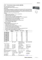
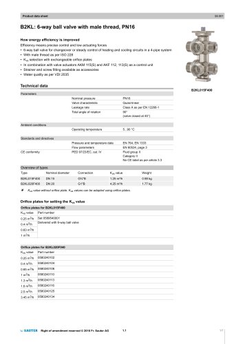
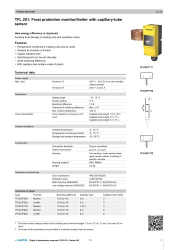
45.012/1 LET4***: Bi-directional wireless controller (868 MHz) How energy efficiency is improved Protected, intelligent solution for optimal energy use. Areas of use As a bi-directional receiving station for the signals from the analogue LRT410 room thermostats and the digital LRA420 and LRA450 room operating units, the LET4*** is used as a single-room controller for every channel and for activating thermal actuators in underfloor heating control systems. The individual controllers communicate using a bi-directional signal. The pulses of the radio thermostats can be individually assigned to the corresponding channels. Features Intelligent bi-directional wireless controllers for heating/cooling Reception frequency: 868.3 MHz Versions with or without LAN connection LEDs for the functions, communication and operating modes One LED per channel for visualisation and confirmation of the channel assignment Emergency function when there is no signal reception Individual configuration for every channel accessible from the outside Integrated pump logic and potential-free output contact With heating/cooling input and potential-free and configurable output Input for monitoring the supply temperature Input for monitoring the relative humidity Technical description Black housing (RAL9005) with transparent cover Versions with 4, 8 and 12 channels Including a transformer for the 24 V version Monitoring of the inputs and state of the controller with LEDs 24 V version with triac outputs for thermal actuators 230 V version with relay outputs for thermal actuators Automatic connection terminal, depending on the channel, 1 or 2 actuators/channel Maximum number of thermal actuators with 12-channel version: 16 SD card for software update accessible from the outside Type Power supply Power consumption 2) 230 V, 4 channels 230 V, 8 channels 230 V, 12 channels 24 V, 4 channels 1) 24 V, 8 channels 1) 24 V, 12 channels 1) Power consumption in stand-by mode Max. power consumption, idle Max. power consumption, idle Number of actuators 3) Max. perm. load Fuse rating 230 V Fuse rating 24 V Radio frequency max. 12.5 W max. 24.5 W max. 36.5 W max. 14.6 W max. 26.6 W max. 38.6 W 2.6 W 2.5 mA at 230 V 250 mA at 24 V 1 or 2 per channel 0.7 A / 24 V / channel 1 A / 230 V / channel 4 A slow 2 A slow 868.3 MHz Pump connection Heating/cooling output Input for monitoring temperature limit 24 V variants 230 V variants Heating/cooling input ECO input 230 V relay output 24 V Triac output Perm. ambient temperature Perm. ambient humidity Ingress protection Protection class 230 V~ 24 V~ Wiring diagram 230 V 24…230 V (N + L) 230 V contacts detected contacts detected 230 V 0.5(0.3) A~ 24 V 1 A~ 0…55 °C
Open the catalog to page 1
Transmission power Range 4) Wiring diagram 24 V Dimension drawing Fitting instructions 24 V version including separate transformer 230 V / 24 V, 42 VA. Power consumption including transformer output Power consumption depends on the number of thermal actuators connected In standard buildings or detached houses, depending on the ambient conditions External active aerial including 5 m of cable with two RJ12 plugs. Only this aerial connection cable may be used. If a different or longer connecting cable is used, operation may be impaired. See fitting instructions P100011074. Repeater for...
Open the catalog to page 2
Anti-jamming function for pump and valves To prevent the pump and the valves from jamming, the anti-jamming function is started once a week. The function is started if one of the outputs has not been addressed for a week. The anti-blocking function switches on the pump for 3 minutes. The actuators are monitored on each channel and are switched on for 20 minutes. The pump and the actuators switch on automatically without advance warning. Emergency mode Emergency mode is intended as a frost-protection facility; for this reason it is active only in heating mode. If no radio signal has been...
Open the catalog to page 3
45.012/4 LET4*** Initial controlled floor heating For a newly-installed underfloor heating system, we recommend heating up the floor slowly. This heating-up period is 36 hours and is divided into three steps. 1st step for 12 hours with a setpoint of 7 °C 2nd step with a setpoint of 12 °C 3rd step with a setpoint of 15 °C If the room temperature is above the setpoint for the corresponding step, the valves are closed. Cooling lock and/or bypass The cooling lock can be activated with parameter P-45. When it is active, this room operating unit (or the room) is not switched to cooling when...
Open the catalog to page 4
Radio communication between controllers Multiple wireless controllers can be combined into a system. A system can comprise a maximum of three wireless controllers. One of these wireless controllers must be defined as the master. The wireless controllers are set as slaves ex works. The communication between the master and slave controllers is performed every 3 minutes. For this function, there is a master button and a system button for addressing the controllers with one another. Before the wireless controller is assigned to a wireless room operating unit, the wireless controller must be...
Open the catalog to page 5
45.012/6 LET4*** Description of the operating buttons and LEDs LEDs Operating buttons Operating buttons Combine up to three wireless controllers into one system. Additionally, I/O boxes and an outside-temperature sensor can be integrated into a system. Set a wireless controller as the master in a system with multiple wireless controllers. One master must be defined for each system. Combine multiple wireless controller channels into one zone or up to a maximum of three zones. Address a wireless room operating unit and a wireless controller. Delete addressing. Add channels to zones or delete...
Open the catalog to page 6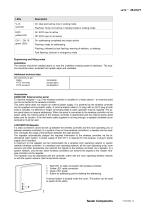
On: dew point active only in cooling mode On: addressing completed and output active Flashing: Temp. limit active in heating mode or cooling mode Flashing: ready for addressing Flashing, followed by fast flashing: warning of deletion, or deleting Fast flashing: channel in emergency mode Engineering and fitting notes Installation The receiver should be installed above or near the underfloor heating system's distributor. The location should be clean, protected from splash water and ventilated. Additional technical data CE conformity as per: Radio RTTE immunity RTTE emission Accessories...
Open the catalog to page 7All Fr. Sauter AG catalogs and technical brochures
-
 SAUTER Catalogue
551 Pages
-
 HSC 120: Room humidistat
3 Pages
-
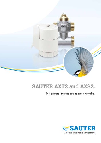 SAUTER AXT2 and AXS2.
8 Pages
-
 Ball valve and actuator.
6 Pages
-
 SAUTER Valveco compact
8 Pages
-
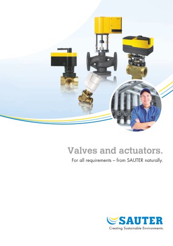 Valves and actuators.
32 Pages
-
 SAUTER vialoq AVM 100
2 Pages
-
 ASM 134: Damper actuator
4 Pages
-
 SAUTER flexotron ® 400
4 Pages
-
 EXG: Active potentiometer
2 Pages
-
 flexotron ® 2000
2 Pages
-
 SAUTER flexotron800
8 Pages
-
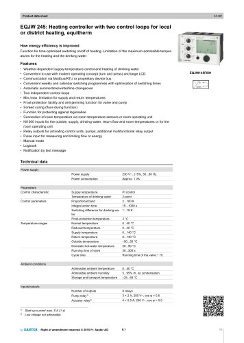 EQJW 24
8 Pages
-
 NRT 101
8 Pages
-
 Thermowells
6 Pages
-
 Indoor air quality
8 Pages
-
 SAUTER EGQ
4 Pages
-
 SAUTER equiflex ® NRT300
4 Pages
-
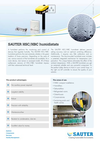 SAUTER HSC/HBC humidistats
2 Pages
-
 DSA: Pressure switch
4 Pages
-
 TFL 201
3 Pages
-
 TUC: Universal thermostat
5 Pages
-
 TLC
TLC2 Pages
-
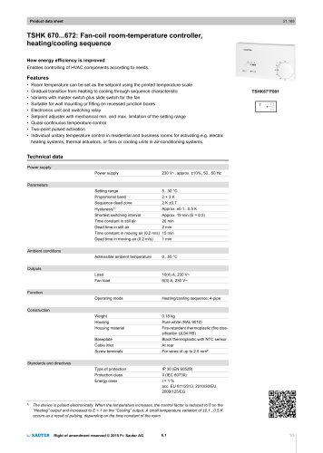 TSHK 670...67
3 Pages
-
 TSHK 621...643
4 Pages
-
 TSO, TSH: Room thermostat
4 Pages
-
 RAK: Universal thermostat
5 Pages
-
 SAUTER FACTS
28 Pages
-
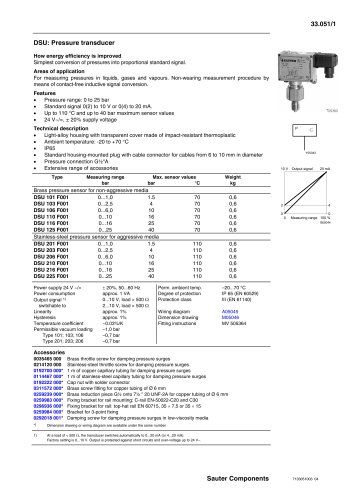 Pressure transducer
3 Pages
-
 Air-flow transducer
2 Pages