Group: Coesia

Catalog excerpts
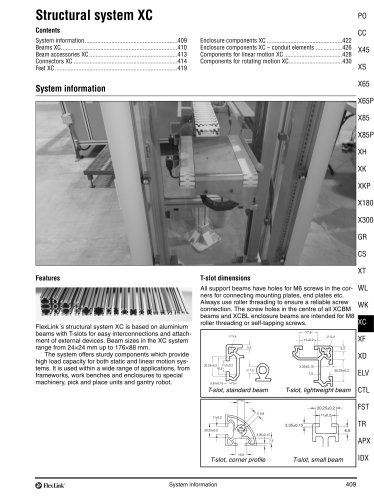
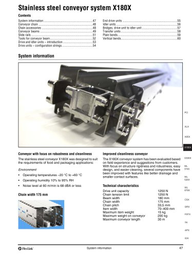
Contents FlexLink conveyor system XW Technical data Design guidelines Installation procedure Chains Conveyor frame components Drive units Double drive units Triple drive units Idler end units Support designs
Open the catalog to page 1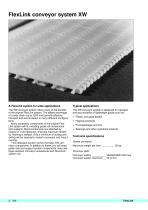
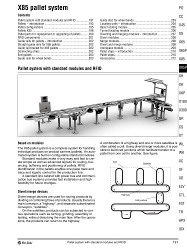
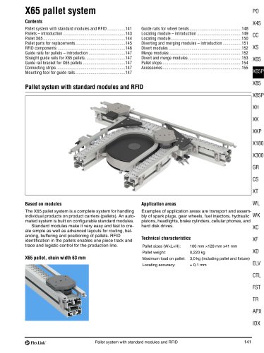
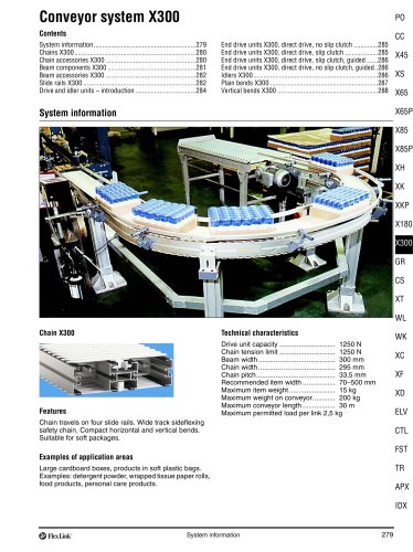
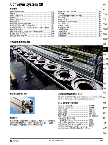
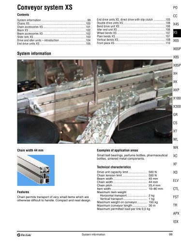
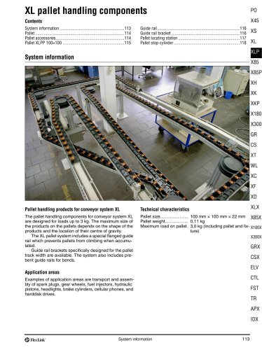
FlexLink conveyor system XW A FlexLink system for wide applications Typical applications The XW conveyor system offers many of the benefits of the original FlexLink system. The added advantage of a wide chain (up to 1200 mm) permits effective transport and accumulation in many different configurations. Many accessory components of the original FlexLink system will fit, including guide rail components and supports. Most components are attached by means of T-slot fasteners, ensuring maximum flexibility. Nothing is welded. Only a minimum of cutting and drilling will be required to install a...
Open the catalog to page 2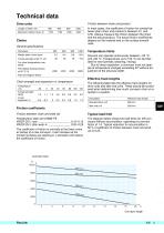
Technical data PO Friction between chain and product Drive units Length of shaft, mm In most cases, the coefficient of friction for contact between plain chain and product is between 0,1 and 0,35. Always measure the friction between the chain and the actual product. The actual friction coefficients depend on the material and on the surface smoothness. Maximum traction force, N Temperature limits Weight (plain chain) kg/m FlexLink can operate continuously between –20 °C and +60 °C. Temperatures up to 100 °C can be tolerated for short periods (cleaning, rinsing). Due to linear expansion, a...
Open the catalog to page 3
Design guidelines Design procedure Chain tension calculations As in all design work it is essential to base the work on a specification of design requirements. Parameters to take into consideration include: • Surface pressure between chain and slide rail There are at least two reasons why you should estimate or calculate the maximum tension of the chain before you decide on a conveyor configuration: • Drive unit capacity • Conveyor width • Tension limit of conveyor chain • Total length • Conveyor speed • Operating temperature Drive unit capacity limit/chain tension limit The required drive...
Open the catalog to page 4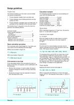
Design guidelines Traction force Calculation example The tension building up in the chain can be divided into several components: The following example involves an accumulating conveyor with the following data: Friction between loaded chain and slide rails. Friction between accumulating products and top surface of chain. Friction between unloaded chain and slide rails, for example on the underside of the conveyor beam. Conveyor speed ____________ 5 m/min Starts and stops ____________ 10/hour Conveyor width_____________ 600 mm Conveyor length ____________ 7 m Friction coefficient µr ________...
Open the catalog to page 5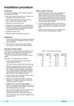
Installation procedure Introduction Basic conveyor structure The method of building an XW conveyor consists of the following basic steps: Assemble the basic conveyor by connecting conveyor frame sections using connecting strips XWCJ 6×280 in the inner slot of the frame profile. (The outer slots should be reserved for connection to the support system, and for other external connections.) Use connecting pieces XLRJ 100 to connect the centre support profiles. Connect support legs and feet to your basic conveyor in accordance with your layout. Try to locate support points close to joints...
Open the catalog to page 6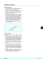
Installation procedure Slide rail and chain 1 2 Secure the slide rails with two plastic screws XWAG 5. See Appendix A, catalogue section APX. Release the friction coupling (slip clutch) so that the drive shaft is free to turn. Install plastic slide rail on all profiles that would otherwise be in direct contact with the chain. Install the chain, one length at a time, starting at the drive unit end. The chain can run in either direction. Feed the chain along the conveyor through the idler unit and back on the return side to the drive unit. Add chain lengths until the total length is...
Open the catalog to page 7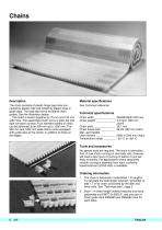
Material specifications The chain consists of plastic hinge-type links connected by plastic rods and locked by plastic snap-in guide clips. The clips also serve as lateral chain guides. See the illustration below. The chain is woven together by 75 mm and 150 mm wide links. The assembled chain forms a wide, flat and tight conveyor surface. Four standard widths of chain can be delivered, from 300 mm up to 1200 mm. The 900 mm and 1200 mm wide chains come equipped with guide clips at the centre, in addition to those at the edges. Technical specifications Chain width ______________...
Open the catalog to page 8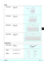
Chain guide clip, right 3904683 Chain guide clip, left
Open the catalog to page 9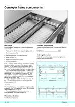
Conveyor frame components Technical specifications Conveyor frame sections are built from the following components: Typical friction between chain and slide rails after runin: • Frame profile (3 m/6 m/cut to any length up to 6 m) • Centre support profile • Hold-down bracket for support profiles Ordering information Slide rail, connecting strips, and connecting sleeves must be ordered separately. • Angle bracket or fastener yoke • Mounting hardware. Each 3 m frame section consists of two frame profiles connected by four cross bars. The conveyor chain slides on the top edges of the frame...
Open the catalog to page 10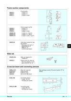
Frame section components XWCF 3 XWCF 6 XWCF L Frame profile Length 3 m Length 6 m Length to order XWCN 3 XWCN 6 XWCN L XWCN 3 D XWCN 6 D XWCN L D Centre support profile Length 3 m Length 6 m Length to order Length 3 m, Type D Length 6 m, Type D Length to order, Type D Hold-down bracket for support profiles Mounting: one each of M6S/MC6S 8×14 BRB 8,4×16 XCAN 8 (see below) Slide rail PAL XWCR 25 U Slide rail, length 25 m UHMW-PE Plastic screw for slide rail Must be ordered in multiples of 25 (25, 50, 75, ...) Cross bar beam and connecting devices XCBL 3×44 XLFA 44 C XCAF 44 XCAN 8 Beam for...
Open the catalog to page 11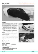
Drive units Note! 0-unit. SEW motor is not included. Description The drive unit is positioned at one end of the conveyor. Two or more sprocket wheels on the drive shaft pull the chain on the top side of the conveyor frame. The chain returns on the bottom side. Support wheels on a separate shaft are used to guide the chain on the return side. The motor drives the sprocket shaft over a chain transmission with a safety clutch. Two configurations are available: with motor on left hand side or on right hand side. A large number of speeds can be obtained by combining a gear ratio and chain...
Open the catalog to page 12All FlexLink catalogs and technical brochures
-
 Conveyor system XW
20 Pages
-
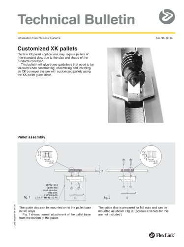
 Customized XK pallets
2 Pages
-
 WLX222
16 Pages
-
 Food and dairy
8 Pages
-
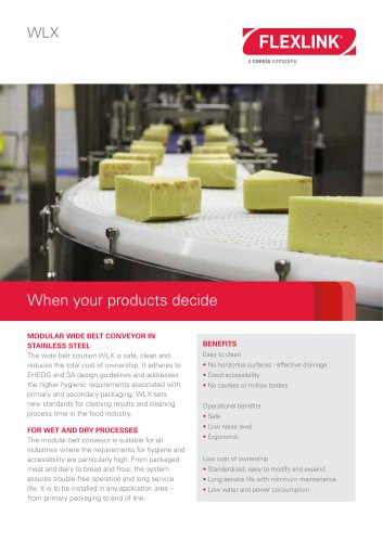 WLX
WLX2 Pages
-
 Enclosures and safety guards
158 Pages
-
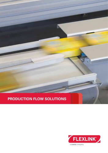 PRODUCTION FLOW SOLUTIONS
8 Pages
-
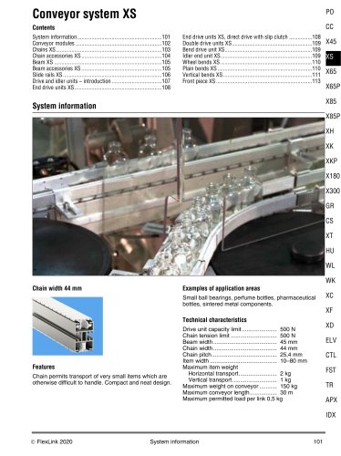 Conveyor system XS
14 Pages
-
 Elevator
4 Pages
-
 Modular plastic belt conveyor WK
14 Pages
-
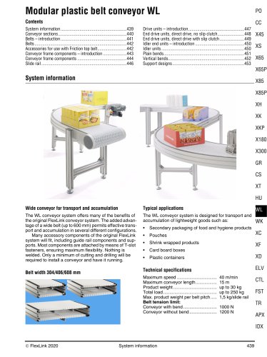 Modular plastic belt conveyor WL
16 Pages
-
 Conveyor system X65
32 Pages
-
 Product overview
498 Pages
-
 Customized XK pallets
2 Pages
-
 GENIUS PCB HANDLING SYSTEM
66 Pages
-
 Product Catalogue
160 Pages
-
 Configurable Components
20 Pages
-
 SMART PCB handling system
12 Pages
-
 GENIUS line
8 Pages
-
 SMART line
4 Pages
-
 Pallet system XTH
4 Pages
-
 Conveyor system WL374X
16 Pages
-
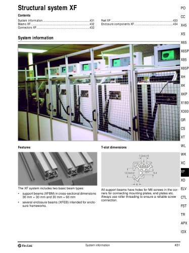 Structural system XF
8 Pages
-
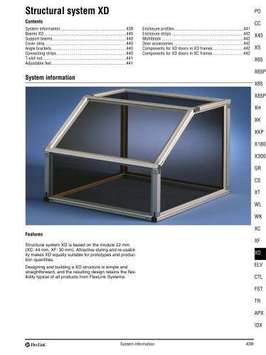 Structural system XD
4 Pages
-
 Spiral elevator
2 Pages
-
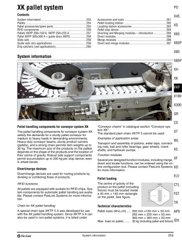 Pallet system XK
16 Pages
-
 Pallet system X85
22 Pages
-
 Conveyor system WL526X
16 Pages
-
 Structural system XC
22 Pages
-
 Conveyor system XLX
8 Pages
-
 Pallet system XT
50 Pages
-
 Pallet system X65
16 Pages
-
 Conveyor system WL678X
16 Pages
-
 Conveyor system X300X
14 Pages
-
 Conveyor system X180X
14 Pages
-
 Conveyor system X85X and X85Y
18 Pages
-
 Profile system MS+
320 Pages
-
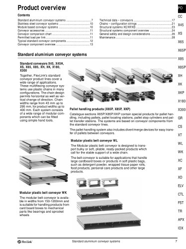 Product overview
24 Pages
-
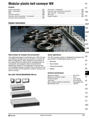 Conveyor system WK
12 Pages
-
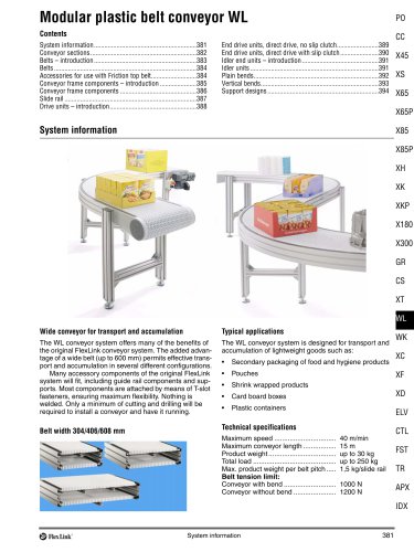 Conveyor System WL
16 Pages
-
 Conveyor System X300
10 Pages
-
 Conveyor System X180
10 Pages
-
 Conveyor System XK
20 Pages
-
 Conveyor System XH
20 Pages
-
 Conveyor System X85
34 Pages
-
 Conveyor System X65
30 Pages
-
 Conveyor System XS
12 Pages
-
 Conveyor System X45
48 Pages


Archived catalogs
-
 Conveyor System XL
28 Pages