Group: Emerson Process Management

Catalog excerpts

Product Bulletin Fisherr i2P-100 Electro-Pneumatic Transducer The Fisher i2P-100 electro-pneumatic transducer, uses a converter module that converts a milliampere input to a proportional pressure output. Both the current input and pressure output range are user-configurable in the field. The converter module uses small parts of minimum mass, which are balanced symmetrically around a pivot point at the center of the mass. This balanced arrangement results in a high performance instrument that reduces sensitivity to vibration. An integral pneumatic relay provides the high capacity necessary to drive pneumatic control valve/actuator assemblies without additional boosters or positioners. The transducer also provides stable, accurate operation when its output is transmitted to small volume chambers, such as a pneumatic positioner or other pneumatic instrument. Reduced sensitivity to vibration, combined with high capacity and first order lag characteristics, make the i2P-100 transducer suitable for direct mounting on control valve/actuator combinations. REPLACEABLE FILTER WITH REMOVABLE ORIFICE INTEGRAL PNEUMATIC RELAY n High Output Capability and Rangeability— The integral output relay volume of the transducer is adequate to drive valve/actuator combinations without requiring a positioner or volume booster. Selectable user field-configurable dip switch setting for output range of 0.14 to 2.3 bar (2 to 33 psi). n Split Range—Selectable user field-configurable Features n Approved for use with Natural Gas—The i2P-100 is approved for use with natural gas as the pneumatic supply. n Low Pneumatic Supply Consumption—The transducer has low pneumatic supply consumption which lowers operating costs. Maximum steady state consumption is less than the 6 SCFH requirement set for the oil and gas industry by the US Environmental Protection Agency (New Source Performance Standards Subpart OOOO, EPAHQQAR20100505). n Single Sealed Device— The i2P-100 has been tested in accordance with ANSI/ISA Standard 12.27.01 (Requirements for Process Sealing Between Electrical Systems and Flammable or Combustible Process Fluids) as a single sealed device. two-way split range, using either half of the standard input signal. n Corrosion Resistant—Separate housing compartments isolate the electronics from the pneumatic process. The electronics module is encased in a rugged plastic shell which helps to prevent damage to the electronics. The printed wiring board and dip switches are conformal coated to help prevent corrosion. Converter module coils have corrosion resistant coating and all flexures are gold plated to provide protection from hostile environments. n Tolerant of Dirty Supply Medium—Free-flow pilot stage design and large internal air passages provide excellent tolerance to dirty pneumatic supply, by reducing the effects of contaminant buildup and erosion. The removable primary orifice and replaceable 5 micrometer filter are easy to remove for service and maintenance.
Open the catalog to page 1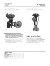
Product Bulletin Figure 2. Fisher i2P-100 Electro-Pneumatic Transducer Mounted on a Sliding-Stem Actuator Figure 1. Fisher i2P-100 Electro-Pneumatic Transducer Mounted on a Rotary Actuator n Easy Maintenance—Modular electronics and converter modules contained in separate housing compartments, isolating the electronics from the process, allow for easy replacement in the field for reduced maintenance time and costs. Valve Stroking Time Figure 3 shows relative times for loading and exhausting an actuator. Stroking time depends upon the size of the actuator, travel, relay characteristics and...
Open the catalog to page 2
Product Bulletin Specifications Frequency Response: Gain is attenuated 3 dB at 3 Hz with transducer output signal piped to a typical instrument input Input Signal Available as standard with 4-20 mA. User configurable by dip switch for split ranging, see table below. Temperature Effect: $0.14% per degrees Celsius ($0.075 per degrees Fahrenheit) of span Output Signal Supply Pressure Effect: 0.2% of full scale output span per psi supply pressure change) Available as standard 0.2 to 1.0 bar (3 to 15 psig), 0.4 to 2.0 bar (6 to 30 psig), or 0.14 to 2.3 bar (2 to 33 psig). User configurable by...
Open the catalog to page 3
Product Bulletin Specifications (continued) Other Classifications/Certifications GOST‐R—Russian GOST‐R INMETRO— National Institute of Metrology, Quality, and Technology (Brazil) KGS—Korea Gas Safety Corporation (South Korea) NEPSI— National Supervision and Inspection Centre for Explosion Protection and Safety of Instrumentation (China) RTN—Russian Rostekhnadzor Contact your Emerson Process Management sales office for classification/certification specific information Construction Materials Housing: J Low-Copper aluminum with polyurethane paint O-rings: Nitrile Diaphragms: Nitrile...
Open the catalog to page 4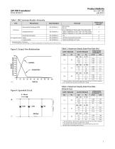
Product Bulletin Table 1. EMC Summary Results—Immunity Port Basic Standard Test Level Burst (fast transients) 4kV Contact 8kV Air 80 to 1000 MHz @ 10V/m with 1 kHz AM at 80% 1400 to 2000 MHz @ 3V/m with 1 kHz AM at 80% 2000 to 2700 MHz @ 1V/m with 1 kHz AM at 80% 1 kV 1 kV (line to ground only, each) I/O signal/control Surge Conducted RF Specification limit = ±1% of span 1. A=No degradation during testing. B = Temporary degradation during testing, but is self-recovering. Table 2. Maximum Steady-State Flow Rate (Air) Figure 3. Output-Time Relationships OUTPUT (% OF i2P-100 OUTPUT SPAN)...
Open the catalog to page 5
Product Bulletin Ordering Information Refer to figure 5 for location of standard mounting holes in the housing. See figures 1 and 2 for typical mounting configurations. Standard mounting hardware is provided for mounting on the actuator, a pipestand, or surface mount. Field wiring connections are made to the terminal block accessible under the housing cap, via the 1/2 NPT conduit connection. Dimensions are shown in figures 5, 6, 7, and 8. To determine what ordering information is required, refer to the Specifications table. Carefully review the description of each specification. Specify the...
Open the catalog to page 6All FISHER REGULATORS catalogs and technical brochures
-
 ™ Control Valves and Instruments
16 Pages
-
 Run with higher performing,
16 Pages
-
 R Series
2 Pages
-
 LP-Gas Technologies
118 Pages
-
 Industrial Regulators
2 Pages
-
 Type 92B Pressure Reducing Valve
16 Pages
-
 Type 630R Relief Valve
8 Pages
-
 Fisher™ 585C Piston Actuators
16 Pages
-
 Type 630 Regulator
16 Pages
-
 Fisher™ YD and YS Control Valves
24 Pages
-
 easy-e Cryogenic Valves
12 Pages
-
 Large ET and ED Valves
20 Pages
-
 1305 Series Regulators
4 Pages
-
 H200 Series Relief Valves
4 Pages
-
 Air Application Map
1 Pages
-
 DeltaV Controller Firewall
11 Pages
-
 CSI 6500 Overview
12 Pages
-
 The Criticality of Cooling
5 Pages
-
 Ovation Security Center
4 Pages
-
 DeltaV Smart Switches
28 Pages
-
 Smartprocess™ Heater
5 Pages
-
 FPSO Industry Solution
2 Pages
-
 LP-31
LP-3196 Pages
-
 CS 200 series
2 Pages
-
 Regulators Mini Catalog
24 Pages
-
 1301F, 1301G
12 Pages
-
 MR95 and MR98
2 Pages
-
 Fisher® D and DA Valves
12 Pages
-
 Fisher® EZ easy-e Control Valve
40 Pages
-
 Fisher® YD and YS Control Valves
24 Pages
-
 Fisher® HPNS Control Valve
36 Pages
-
 Fisher® HP Series Control Valves
28 Pages
-
 Fisher® CAV4 Control Valve
28 Pages
-
 Fisher® 377 Trip Valve
20 Pages
-
 EZR Pressure Reducing Regulator
36 Pages
-
 630 Regulator
16 Pages
-
 627F Pressure Reducing Regulator
12 Pages
-
 ACE97 Pad-Depad Valve
16 Pages
-
 310A Pressure Reducing Regulator
16 Pages
-
 S200 series
32 Pages
-
 R622 series
8 Pages
-
 Type HSR Pressure Regulators
20 Pages
-
 cs200 series
40 Pages
-
 CS400 Series
60 Pages
-
 167D Series Switching Valves
8 Pages


Archived catalogs
-
 Vapor Pressures of LP-Gas
1 Pages
-
 Pipe and Tubing Sizing
1 Pages
-
 Average Properties of LP-Gas
1 Pages
-
 Pressure Equivalents
1 Pages


