Group: Emerson Process Management

Catalog excerpts

Bulletin 71.1:CS400 January 2012 CS400 Series Commercial / Industrial Pressure Reducing Regulators TYPICal CS400 regulaTOr P1190 P1426 P1424 TYPICal CS404 regulaTOr WITh INTegral TYPe vSx4 SlaM-ShuT MOdule TYPICal CS403 regulaTOr WITh INTegral True-MONITOr™ regulaTOr Figure 1. Typical CS400 Pressure Reducing Regulator Features and Benefits • Wide Variety of Body Sizes and End Connections • Fixed Factor / PFM Accuracy Capabilities • Only Standard Tools Required for Pressure Adjustment and Orifice Removal • Easy to Maintain D103134X012 • Field Convertible from Internal Sensing to External Sensing for Wide-Open Monitor Construction • Available in Gray Cast Iron, Ductile Iron, and Steel Body Materials www.fisherregulators.com
Open the catalog to page 1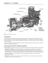
Bulletin 71.1:CS400 adJuSTINg SCreW STABILIZER CONTrOl SPrINg dIaPhragM head relIef valve STeM relIef valve SeaT OrIfICe valve STeM valve dISK lever lOWer CaSINg PreSSure reTaININg Plug (dO NOT reMOve If uNIT IS PRESSURIZED) P1003 Figure 2. Typical CS400 Internal View Introduction The CS400 Series direct-operated, spring-loaded regulators have been engineered to fit a multitude of pressurereducing applications including commercial and industrial installations. This flexibility is provided by the numerous body sizes and end connections, outlet pressure settings, orifice sizes, as well as the...
Open the catalog to page 2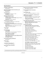
Bulletin 71.1:CS400 Specifications Available Configurations See Figure 3 Spring Case Vent and Body Orientation See Figures 15 and 16 Body Sizes, Material, End Connections, and Pressure Rating(1) See Table 1 External Registration Connection 3/4 NPT Inlet Pressure Tap 1/4 NPT restricted to 0.054-inch / 1.37 mm Inlet Pressures(1) Emergency: 175 psig / 12.1 bar Operating: See Table 2 Maximum Outlet Pressure(1) Casing: 25 psig / 1.7 bar To Avoid Internal Parts Damage: 5 psig / 0.34 bar over set pressure Operating: 5.5 psig / 380 mbar Outlet Pressure Ranges(1) 3.5-inches w.c. to 5.5 psig / 9 to...
Open the catalog to page 3
Specifications (Continued) Type TM600 True-Monitor™ Actuator (continued) Monitor Stem: 302 Stainless Middle Diaphragm Retainer: Zinc-plated steel Control Spring: 302 Stainless steel Vent Screen: 18-8 Stainless steel Vent Retaining Ring: Zinc-plated steel Adjusting Screw: Aluminum Type VSX4 Slam-shut Device Diaphragm Case, Spring Case, Diaphragm Plate, and Valve Stem: Aluminum Diaphragm and Disk: Nitrile (NBR) Control Spring: Music Wire or 302 Stainless Vent Screen: 18-8 Stainless Type VSX4 Slam-shut Device (continued) Vent Screen Retainer: Zinc-plated steel Adjusting Screw: Aluminum...
Open the catalog to page 4
Table 2. Inlet Pressure Ratings and Flow and Sizing Coefficients Table 3. Outlet Pressure Ranges Table 4. Approximate Internal Relief Valve Start-to-Discharge Pressure Above Setpoint Table 5. Type CS403 Overpressure Protection Benefits Vs. Backup Orifice Device
Open the catalog to page 5
Table 6. Type CS403 Regulator and Integral Monitor Outlet Pressure Ranges Table 7. Type CS404 Regulator and Slam-Shut OPSO Pressure Ranges Table 8. Type CS404 Regulator and Slam-shut OPSO and UPSO Pressure Ranges
Open the catalog to page 6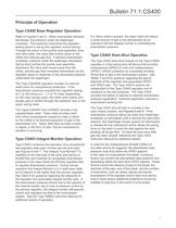
Bulletin 71.1:CS400 Principle of Operation Type CS400 Base Regulator Operation Refer to Figures 4 and 5. When downstream demand decreases, the pressure under the diaphragm increases. This pressure overcomes the regulator setting (which is set by the regulator control spring). Through the action of the pusher post assembly, lever, and valve stem, the valve disk moves closer to the orifice and reduces gas flow. If demand downstream increases, pressure under the diaphragm decreases. Spring force pushes the pusher post assembly downward, the valve disk moves away from the orifice, and the gas...
Open the catalog to page 7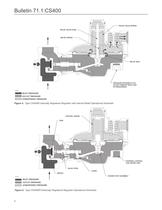
Bulletin 71.1:CS400 relief valve sPRING relief valve stem relief sPRING relief seat Pressure Retaining PLUG (DO NOt REMOVE WHILE UNIT IS PRESSURIZED) M1060 inlet pressure outlet pressure atmospheric pressure Figure 4. Type CS400IR Internally Registered Regulator with Internal Relief Operational Schematic control spring DISK RE External Control Line (Sense Line) E E valve stem ESSURE RE lever orifice pusher post assembly M1059 inlet pressure outlet pressure E atmospheric pressure Figure 5. Type CS400ER Externally Registered Regulator Operational Schematic 8
Open the catalog to page 8
CS400 Series January 2008 March 2009 Type CS403IT with True Monitor, Bulletin 71.1:CS400 Internal Pressure Registration, and Token Relief CONTrOl SPrINg adJuSTINg SCreW MONITOr dISK guIded STeM OPeNINg SPrINg exTerNal October 2008 MONITOr lever CONTrOl lINe Plug CONTrOl SPrINg dISK exTerNal CONTrOl lINe Plug (dO NOT reMOve WhIle uNIT IS PRESSURIZED) valve STeM valve STeM Type CS403ET with True Monitor, External Pressure Registration, and Token Relie OrIfICe lever INLET PRESSURE INTegral MONITOr OUTLET PRESSURE ATMOSPHERIC PRESSURE PrIMarY regulaTOr M1061 M1061 PuSher POST ASSEMBLY INleT...
Open the catalog to page 9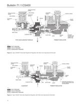
Bulletin 71.1:CS400 uPSO adJuSTINg SCreW uPSO SPrINg OPSO adJuSTINg SCreW adJuSTINg SCreW SlaM-ShuT OrIfICe OPSO SPrINg October 2008 SlaM-ShuT veNT CONTrOl SPrINg OrIfICe relIef SPrINg Type CS404ET with Slam-Shut Module, External Pressure Registration, and Token R RESET KNOB SlaM-ShuT dISK valve STeM lever exTerNal CONTrOl lINe CONNeCTION (SENSE LINE) PuSher POST dISK PrIMarY regulaTOr TYPe vSx4 SlaM-ShuT MOdule M1063 INleT PreSSure INLET PRESSURE OuTleT PreSSure OUTLET PRESSURE aTMOSPherIC PreSSure ATMOSPHERIC PRESSURE Figure 8. Type CS404ET Externally Registered Regulator with Slam-shut...
Open the catalog to page 10
Bulletin 71.1:CS400 Installation Internal Relief “R” The CS400 Series regulators may be installed in any position. However, the spring case vent should be pointed downward. If gas escaping through the CS400 Series internal relief valve could constitute a hazard, the spring case vent must be piped to a location where escaping gas will not be hazardous. If the vented gas will be piped to another location, use obstruction-free tubing or piping at least equal in size to the vent, and the end of the vent pipe must be protected from anything that might clog it. Regulators with External...
Open the catalog to page 11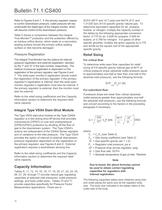
Bulletin 71.1:CS400 Refer to Figures 6 and 7. If the primary regulator ceases to control downstream pressure, outlet pressure will rise underneath the diaphragm of the integral monitor, which will assume control of the downstream pressure. Table 5 shows a comparison between the integral True-MonitorTM protection and the protection offered by an backup orifice device, which seals on a secondary seating surface should the primary orifice seating surface or disk become damaged. scfh (60°F and 14.7 psia) and Nm³/h (0°C and 1.01325 bar) of 0.6 specific gravity natural gas. To determine...
Open the catalog to page 12All FISHER REGULATORS catalogs and technical brochures
-
 ™ Control Valves and Instruments
16 Pages
-
 Run with higher performing,
16 Pages
-
 R Series
2 Pages
-
 LP-Gas Technologies
118 Pages
-
 Industrial Regulators
2 Pages
-
 Type 92B Pressure Reducing Valve
16 Pages
-
 Type 630R Relief Valve
8 Pages
-
 Fisher™ 585C Piston Actuators
16 Pages
-
 Type 630 Regulator
16 Pages
-
 Fisher™ YD and YS Control Valves
24 Pages
-
 easy-e Cryogenic Valves
12 Pages
-
 Large ET and ED Valves
20 Pages
-
 1305 Series Regulators
4 Pages
-
 H200 Series Relief Valves
4 Pages
-
 Air Application Map
1 Pages
-
 DeltaV Controller Firewall
11 Pages
-
 CSI 6500 Overview
12 Pages
-
 The Criticality of Cooling
5 Pages
-
 Ovation Security Center
4 Pages
-
 DeltaV Smart Switches
28 Pages
-
 Smartprocess™ Heater
5 Pages
-
 FPSO Industry Solution
2 Pages
-
 LP-31
LP-3196 Pages
-
 CS 200 series
2 Pages
-
 Regulators Mini Catalog
24 Pages
-
 1301F, 1301G
12 Pages
-
 MR95 and MR98
2 Pages
-
 Fisher® D and DA Valves
12 Pages
-
 Fisher® EZ easy-e Control Valve
40 Pages
-
 Fisher® YD and YS Control Valves
24 Pages
-
 Fisher® HPNS Control Valve
36 Pages
-
 Fisher® HP Series Control Valves
28 Pages
-
 Fisher® CAV4 Control Valve
28 Pages
-
 Fisher® 377 Trip Valve
20 Pages
-
 EZR Pressure Reducing Regulator
36 Pages
-
 630 Regulator
16 Pages
-
 627F Pressure Reducing Regulator
12 Pages
-
 ACE97 Pad-Depad Valve
16 Pages
-
 310A Pressure Reducing Regulator
16 Pages
-
 S200 series
32 Pages
-
 R622 series
8 Pages
-
 Type HSR Pressure Regulators
20 Pages
-
 cs200 series
40 Pages
-
 167D Series Switching Valves
8 Pages


Archived catalogs
-
 Vapor Pressures of LP-Gas
1 Pages
-
 Pipe and Tubing Sizing
1 Pages
-
 Average Properties of LP-Gas
1 Pages
-
 Pressure Equivalents
1 Pages


