Group: Emerson Process Management

Catalog excerpts

Bulletin 71.1:CS200 September 2012 cs200 series commercial / Industrial pressure reducing regulators P1188 Figure 1. Typical CS200 Pressure Reducing Regulator Features and Benefits • Wide Range of Body Sizes and End Connections • Easy to Install and Maintain • Fixed Factor Accuracy (PFM Approved) • Secondary Seat Protection provides a secondary seating and disk surface in the event that damage to the primary disk or orifice seat or debris in the flow path inhibit lockup. D103133X012 • Only Standard Tools Required for Pressure Adjustment and Orifice Removal • Application Flexibility including Internal Relief, Non-Relieving, and Secondary Seat™ Protection www.fisherregulators.com
Open the catalog to page 1
Bulletin 71.1:CS200 adjusting screw relief valve stem stabilizer diaphragm head RELIEF VALVE SPRING orifice spring seat stem relief valve seat lever valve disk pusher post assembly pressure retaining plug (do not remove) body Figure 2. Typical CS200 Pressure Reducing Regulator Cut-Away View Introduction The CS200 Series direct-operated, spring-loaded regulators have been engineered to fit a multitude of pressure-reducing applications including commercial and industrial installations. This flexibility is provided by the numerous body sizes, outlet pressure settings, and orifice sizes. Ease...
Open the catalog to page 2
Available Configurations Type CS200IN: Basic construction with Internal pressure registration and Non-Relieving diaphragm assembly. Type CS200IR: Basic construction with Internal pressure registration and Relieving diaphragm assembly. Type CS205IN: Type CS200IN with Secondary Seat™ Protection Type CS205IR: Type CS200IR with Secondary Seat Protection Type CS206IR: Type CS200IR with Secondary Seat Protection with bleed to indicate Secondary Body Sizes, Material, End Connections, and To Avoid Internal Parts Damage: 5 psig / 0.35 bar differential above outlet pressure setting Outlet Pressure...
Open the catalog to page 3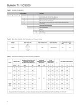
Table 1. Available Configuration Table 2. Body Sizes, Material, End Connection, and Pressure Rating Table 3. Inlet Pressure Ratings and Flow and Sizing Coefficients
Open the catalog to page 4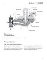
March 2008 Type CS200IR Regulator with Relief Bulletin 71.1:CS200 Type CS200 March 2008 Type CS200IR Regulator with Relief WIRE SEAL (OPTIONAL) relief valve stem control spring relief valve spring disk valve stem DIAPHRAGM relief seat PRESSURE RETAINING PLUG (DO NOT REMOVE) MXXXX lever orifice pusher post assembly M1131 INLET PRESSURE OULET PRESSURE ATMOSPHERIC PRESSURE Figure 3. Type CS200IR Pressure Reducing Regulator with Internal Relief Principle of Operation Type CS200 Base Regulator Operation Refer to Figure 3. When downstream demand decreases, the pressure under the diaphragm...
Open the catalog to page 5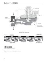
Bulletin 71.1:CS200 control sprIng relIef valve stem valve stem CONTROL SPRING RELIEF V LVE STEM March 2008 Type CS200IR Regulator with Relief VALVE STEM relIef valve sprIng secondary CONDARY SEATseat detaIl DETAIL relIef seat pressure retaInIng plug (do not remove) secondary seat™ detaIled vIew prImary dIsk secondary orIfIce seatIng surface prImary orIfIce seatIng surface normal operatIon normal lockup secondary seatIng surface secondary seat lockup TyPE CS206 secondary seat wIth metal to metal bleed CP200 Series with Secondary SeatTM Protection M1132 Inlet pressure...
Open the catalog to page 6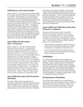
Bulletin 71.1:CS200 CS200 Series with Internal Relief Refer to Figure 3. The option for internal relief is offered on the Types CS200 and CS205 and is standard on the Type CS206. Internal relief is used to help minimize overpressure. Any outlet pressure above the start-todischarge point of the non-adjustable relief spring moves the diaphragm off of the relief seat, allowing excess pressure to discharge through the vent. For approximate start-to-discharge values, see Table 5. If emergency conditions should exist that prevent normal operation of the regulator or internal relief valve, the...
Open the catalog to page 7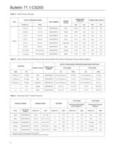
Table 4. Outlet Pressure Ranges Table 5. Types CS200 and CS205 Approximate Internal Relief Valve Start-to-Discharge Pressure Above Setpoint Table 6. Secondary Seat™ Outlet Pressures
Open the catalog to page 8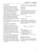
Internal Relief The internal relief provided by the Type CS200IR limits the total outlet pressure to values shown in Relief Tables 8, 11, 16, and 21. This internal relief may be adequate, however, if an additional pressure relief is required to maintain downstream pressure at the desired maximum level, an additional relieving or pressure limiting device should be installed to protect downstream equipment. Overpressuring any portion of a regulator or associated equipment may cause leakage, parts damage, or personal injury due to bursting of pressure-containing parts or explosion of...
Open the catalog to page 9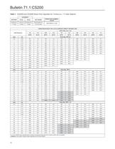
Table 7. CS200IN and CS200IR Series Flow Capacities for 7-inches w.c. /17 mbar Setpoint CAPACITIES IN SCFH / Nm3/h OF 0.6 SPECIFIC GRAVITY NATURAL GAS Blank areas indicate where maximum operating inlet pressure for a given orifice size is exceeded. Gray areas indicate limited capacities due to boost effects.
Open the catalog to page 10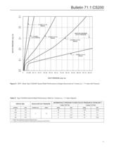
Bulletin 71.1:CS200 3/ 0.21 1/2-Inch / 13 mm orIfIce 2.5 / 0.17 OuTLET PRESSuRE, psig / bar ansI b109.4 maxImum outlet pressure 3/8-Inch / 9.5 mm orIfIce 2/ 0.14 1/4-INCH / 6.4 mm orIfIce 3/16-INCH / 4.8 mm orIfIce 1.5 / 0.10 1/8-Inch / 3.2 mm orIfIce 1/ 0.07 0.5 / 0.34 0 10 / 0.69 20 / 1.4 30 / 2.1 40 / 2.8 50 / 3.4 60 / 4.1 70 / 4.8 80 / 5.5 90 / 6.2 100 / 6.9 110 / 7.6 120 / 8.3 INLET PRESSuRE, psig / bar Figure 5. NPS 1 Body Type CS200IR Typical Relief Performance (Linkage Disconnect) at 7 inches w.c. / 17 mbar Set Pressure Table 8. Type CS200IR Internal Relief Performance Table for...
Open the catalog to page 11
Table 9. CS200IN and CS200IR Series Flow Capacities for 11 inches w.c. /'27 mbar Setpoint CAPACITIES IN SCFH / Nm3/h OF 0.6 SPECIFIC GRAVITY NATURAL GAS Blank areas indicate where maximum operating inlet pressure for a given orifice size is exceeded. Gray areas indicate limited capacities due to boost effects.
Open the catalog to page 12All FISHER REGULATORS catalogs and technical brochures
-
 ™ Control Valves and Instruments
16 Pages
-
 Run with higher performing,
16 Pages
-
 R Series
2 Pages
-
 LP-Gas Technologies
118 Pages
-
 Industrial Regulators
2 Pages
-
 Type 92B Pressure Reducing Valve
16 Pages
-
 Type 630R Relief Valve
8 Pages
-
 Fisher™ 585C Piston Actuators
16 Pages
-
 Type 630 Regulator
16 Pages
-
 Fisher™ YD and YS Control Valves
24 Pages
-
 easy-e Cryogenic Valves
12 Pages
-
 Large ET and ED Valves
20 Pages
-
 1305 Series Regulators
4 Pages
-
 H200 Series Relief Valves
4 Pages
-
 Air Application Map
1 Pages
-
 DeltaV Controller Firewall
11 Pages
-
 CSI 6500 Overview
12 Pages
-
 The Criticality of Cooling
5 Pages
-
 Ovation Security Center
4 Pages
-
 DeltaV Smart Switches
28 Pages
-
 Smartprocess™ Heater
5 Pages
-
 FPSO Industry Solution
2 Pages
-
 LP-31
LP-3196 Pages
-
 CS 200 series
2 Pages
-
 Regulators Mini Catalog
24 Pages
-
 1301F, 1301G
12 Pages
-
 MR95 and MR98
2 Pages
-
 Fisher® D and DA Valves
12 Pages
-
 Fisher® EZ easy-e Control Valve
40 Pages
-
 Fisher® YD and YS Control Valves
24 Pages
-
 Fisher® HPNS Control Valve
36 Pages
-
 Fisher® HP Series Control Valves
28 Pages
-
 Fisher® CAV4 Control Valve
28 Pages
-
 Fisher® 377 Trip Valve
20 Pages
-
 EZR Pressure Reducing Regulator
36 Pages
-
 630 Regulator
16 Pages
-
 627F Pressure Reducing Regulator
12 Pages
-
 ACE97 Pad-Depad Valve
16 Pages
-
 310A Pressure Reducing Regulator
16 Pages
-
 S200 series
32 Pages
-
 R622 series
8 Pages
-
 Type HSR Pressure Regulators
20 Pages
-
 CS400 Series
60 Pages
-
 167D Series Switching Valves
8 Pages


Archived catalogs
-
 Vapor Pressures of LP-Gas
1 Pages
-
 Pipe and Tubing Sizing
1 Pages
-
 Average Properties of LP-Gas
1 Pages
-
 Pressure Equivalents
1 Pages


