Group: Emerson Process Management

Catalog excerpts

Bulletin 71.2:310A January 2009 Type 310A-32A Pressure Reducing Regulator and Type 310A-32A-32A Working Monitor Regulator Introduction The Type 310A pilot-operated high-pressure regulator (Figure 1) is used where high capacity and accurate control are essential. This regulator includes one Type 32A pilot assembly mounted on the main valve for pressure reducing or wide-open monitoring applications, or two Type 32A pilots mounted on the main valve for working monitor applications. Features • Accurate Control—Molded pilot diaphragms provide a narrow proportional band and registration of outlet pressure on the main diaphragm allows excellent control sensitivity. • Tight Shutoff—Throttling-sleeve design with Polytetrafluoroethylene (PTFE) seat in the body ensures positive shutoff. • High Capacity—Straight-through flow passage allows exceptionally high capacities and stable operation. W6278 Figure 1. Type 310A Regulator with Type 32A Pilot • Fast Speed of Response—Designed to meet stringent speed of response requirements for turbine startup and fuel gas applications. • Minimum Installation Space Required—Since main valve design incorporates actuator spring, less installation space is needed for the Type 310A than for other regulators of comparable capacity. D102066X012 • Reduced Relief Requirements—Optional restricted trim helps reduce relief valve size requirements; the regulator is easily converted to full capacity by changing the trim, if flow conditions increase. www.emersonprocess.com/regulators
Open the catalog to page 1
Bulletin 71.2:310A Specifications Available Congurations Type 310A-32A: Type 310A main valve with one Type 32A pilot for standard pressure-reducing and wide-open monitoring applications Type 310A-32A-32A: Type 310A main valve with two Type 32A pilots for working monitor applications Body Sizes and End Connection Styles 1-inch body with NPT ends; and 1, 2, 3, 4, or 4 x 6-inch (DN 25, 50, 80, 100, and 100 x 150) body with CL300 RF or CL600 RF anged ends Maximum Inlet and Pilot Supply Pressures(1) NPT and CL600 RF: 1500 psig (103 bar) CL300 RF: 750 psig (51,7 bar) Maximum Pressure...
Open the catalog to page 2
Bulletin 71.2:310A PILOT DIAPHRAGM PLATE AND YOKE ASSEMBLY PILOT Control spring BLEED VALVE FIXED RESTRICTION BOTTOM DIAPHRAGM RELAY SEAT TOP DIAPHRAGM MAIN VALVE DIAPHRAGM THROTTLING SLEEVE MAIN VALVE SPRING E0696 STATIONARY VALVE PLUG INLET PRESSURE OUTLET PRESSURE atmospheric pressure LOADING PRESSURE PILOT SUPPLY PRESSURE Figure 2. Type 310A-32A Regulator Operational Schematic Principle of Operation Single-Pilot Regulator (Figure 2) The regulator inlet pressure enters the pilot through the external pilot supply line and is utilized as the supply pressure for the pilot. The setting of...
Open the catalog to page 3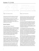
Bulletin 71.2:310A E0694 E0695 Figure 3. Typical Wide-Open Monitor Figure 4. Typical Working Monitor throttling sleeve toward the stationary valve plug to decrease the gas ow to the downstream system. of the Type 32A monitoring pilot. A plug in both the working and monitoring pilots makes the internal bleed nonfunctional. A restriction placed in the external tubing between the diaphragm loading pressure and the intermediate pressure acts as a downstream bleed. The top diaphragm in the pilot acts as a sealing member for the loading chamber and as a balancing member to the bottom diaphragm....
Open the catalog to page 4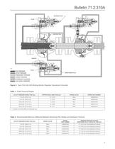
Bulletin 71.2:310A WORKING PILOT PLUG RESTRICTION SPACER E0693 INLET PRESSURE PLUG MONITORING PILOT OUTLET PRESSURE ATMOSPHERIC PRESSURE LOADING PRESSURE INTERMEDIATE PRESSURE PILOT SUPPLY PRESSURE Figure 5. Type 310A-32A-32A Working Monitor Regulator Operational Schematic Table 1. Outlet Pressure Ranges OUTLET PRESSURE RANGE, PSIG (bar) SPRING COLOR SPRING PART NUMBER 10 to 20 (0,69 to 1,4) PROPORTIONAL BAND, PSIG (bar) 0.5 (0,03) Silver 1D809627022 10 to 100 (0,69 to 6,9) 2 (0,14) Yellow 1E392527022 100 to 250 (6,9 to 17,2) 5 (0,34) Blue 1D387227022 250 to 600 (17,2 to 41,4) 12 (0,83)...
Open the catalog to page 5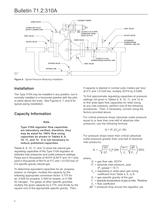
Bulletin 71.2:310A LOADING TUBING HAND VALVE 1/4-INCH NPT PILOT SUPPLY CONNECTION VENT VALVE LOCATE 6 TO 10 PIPE DIAMETERS FROM VALVE OUTLET VENT VALVE BLOCK VALVE HAND VALVE BLOCK VALVE ALTERNATE DOWNSTREAM CONTROL LINE TAP 1/2-INCH (13 mm) DOWNSTREAM CONTROL LINE BYPASS VALVE VENT VALVE BYPASS LINE 24B4134 B2444 Figure 6. Typical Pressure Reducing Installation Installation The Type 310A may be installed in any position, but is normally installed in a horizontal pipeline with the pilot or pilots above the body. See Figures 6, 7, and 8 for typical piping installation. Capacity Information...
Open the catalog to page 6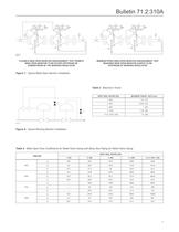
FLEXIBLE WIDE-OPEN MONITOR ARRANGEMENT THAT PERMITS WIDE-OPEN MONITOR TO BE EITHER UPSTREAM OR DOWNSTREAM OF THE WORKING REGULATOR Figure 7. Typical Wide-Open Monitor installation MINIMUM PIPING WIDE-OPEN MONITOR ARRANGEMENT THAT REQUIRES WIDE-OPEN MONITOR ALWAYS TO BE UPSTREAM OF WORKING REGULATOR Table 3. Maximum Travel Figure 8. Typical Working Monitor Installation Table 4. Wide-Open Flow Coefficients for Relief Valve Sizing with Body Size Piping for Relief Valve Sizing
Open the catalog to page 7
Table 5. Regulating Flow Coefficients for Body Size Piping Table 6. Regulating Flow Coefficients for 2:1 Swaged Piping and 100% Trim Table 7. IEC Sizing Coefficients
Open the catalog to page 8
Table 8. 1-inch (DN 25) Body Capacities with 100% Trim and Body Size Piping (Thousands of SCFH (Nrrf/h)) of 0.6 Specific Gravity Gas) Table 8. 1-inch (DN 25) Body Capacities with 100% Trim and Body Size Piping (continued)
Open the catalog to page 9
Table 9. 2-inch (DN 50) Body Capacities with 100% Trim and Body Size Piping (Thousands ofSCFH (Nrrf/h)) of 0.6 Specific Gravity Gas) Table 9. 2-inch (DN 50) Body Capacities with 100% Trim and Body Size Piping (continued)
Open the catalog to page 10
Table 10. 3-inch (DN 80) Body Capacities with 100% Trim and Body Size Piping (Thousands ofSCFH (Nrrf/h)) of 0.6 Specific Gravity Gas) Table 10. 3-inch (DN 80) Body Capacities with 100% Trim and Body Size Piping (continued)
Open the catalog to page 11All FISHER REGULATORS catalogs and technical brochures
-
 ™ Control Valves and Instruments
16 Pages
-
 Run with higher performing,
16 Pages
-
 R Series
2 Pages
-
 LP-Gas Technologies
118 Pages
-
 Industrial Regulators
2 Pages
-
 Type 92B Pressure Reducing Valve
16 Pages
-
 Type 630R Relief Valve
8 Pages
-
 Fisher™ 585C Piston Actuators
16 Pages
-
 Type 630 Regulator
16 Pages
-
 Fisher™ YD and YS Control Valves
24 Pages
-
 easy-e Cryogenic Valves
12 Pages
-
 Large ET and ED Valves
20 Pages
-
 1305 Series Regulators
4 Pages
-
 H200 Series Relief Valves
4 Pages
-
 Air Application Map
1 Pages
-
 DeltaV Controller Firewall
11 Pages
-
 CSI 6500 Overview
12 Pages
-
 The Criticality of Cooling
5 Pages
-
 Ovation Security Center
4 Pages
-
 DeltaV Smart Switches
28 Pages
-
 Smartprocess™ Heater
5 Pages
-
 FPSO Industry Solution
2 Pages
-
 LP-31
LP-3196 Pages
-
 CS 200 series
2 Pages
-
 Regulators Mini Catalog
24 Pages
-
 1301F, 1301G
12 Pages
-
 MR95 and MR98
2 Pages
-
 Fisher® D and DA Valves
12 Pages
-
 Fisher® EZ easy-e Control Valve
40 Pages
-
 Fisher® YD and YS Control Valves
24 Pages
-
 Fisher® HPNS Control Valve
36 Pages
-
 Fisher® HP Series Control Valves
28 Pages
-
 Fisher® CAV4 Control Valve
28 Pages
-
 Fisher® 377 Trip Valve
20 Pages
-
 EZR Pressure Reducing Regulator
36 Pages
-
 630 Regulator
16 Pages
-
 627F Pressure Reducing Regulator
12 Pages
-
 ACE97 Pad-Depad Valve
16 Pages
-
 S200 series
32 Pages
-
 R622 series
8 Pages
-
 Type HSR Pressure Regulators
20 Pages
-
 cs200 series
40 Pages
-
 CS400 Series
60 Pages
-
 167D Series Switching Valves
8 Pages


Archived catalogs
-
 Vapor Pressures of LP-Gas
1 Pages
-
 Pipe and Tubing Sizing
1 Pages
-
 Average Properties of LP-Gas
1 Pages
-
 Pressure Equivalents
1 Pages


