Group: FINETEK

Catalog excerpts
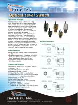
Operational Principle Refraction index of plastic and air varies in big range. Infrared light can be easily reflected totally between plastic and air. In contrast, infrared light would totally penetrate through plastic while plastic and liquid are taken place. Optical switch operates by sensing the difference of refraction index between various mediums, which causes different degree of refraction and penetration. When dry, the transmitted light is reflected by the prism back to the receiver. When the sensor is wetted in liquid, only part of the transmitted light would be reflected back to the receiver while most is lost into the liquid. The received light then changes the signal and controls the switching accordingly. Optical switch is equipped with infrared source and receiver. They are to detect and verify the status of infrared light reflection and penetration between the mediums in order to trigger the alarm output. Product Dimension PC or Polysulfone Product Feature NPN, PNP open collector output to energize relay or PLC. Enclosure material of PC, Polysulfone, SUS304 for acidity and alkaline; applicable in grease, waste water, liquid solution, liquor, alcohol...etc. Over-current and reverse polarity protected LED Status indication. Product Specification 1. Material: PC, Polysulphone or SUS304, SUS316 2. Protection: IP68 3. Operation Temperature: -10~125BC 4. Ambient Temperature: -10~80BC 5. Ambient light: Max. 5000 Lux (visible light) 6. Operation Pressure: Max.10kg/cm2(PC,Polysulfone) Max.40kg/cm2(SUS304) 7. Power Supply: 10~28 Vdc 8. Load Current: Max. Load 100mA 9. Overload Current Protection: 100mA(3/8"G/PF) 10. Connection Thread: M12 x 1 or 3/8"G(PF)or 3/8"(NPT) 11. Lead Wire: 2m CABLE(dia. 3.8) 3C PVC 22 AWG; custom made if over 2m
Open the catalog to page 1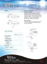
Application Example NPN output Brown LOAD PNP output Brown Black LOAD Liquid Level Control: In Fig.4(a) , two optical switches are installed individually in upper and lower level of the tank. When liquid rises to cover the upper optical switch, it will stop fill in liquid. When liquid drops down and lower optical switch is not covered by liquid, it will start filling up. Liquid has to be maintained in between upper and lower optical switches. Motor Protection: In Fig.4(b) , optical switch is installed in lower level of the tank to prevent pump burning caused by the lack of water/liquid....
Open the catalog to page 2All FineTek Co. catalogs and technical brochures
-
 EFX By-Pass Level Transmitter
34 Pages
-
 EPD Electromagnetic Flow Meter
28 Pages
-
 Tuning Fork Level Switch
32 Pages
-
 Ultrasonic Level Transmitter
8 Pages
-
 Ultrasonic Level Transmitter
8 Pages
-
 Temperature Transmitter
5 Pages
-
 Thermocouple
12 Pages
-
 Vibrating point level switch
14 Pages
-
 SA Capacitance Level Switch
18 Pages
-
 SE Rotary Paddle Level Switch
15 Pages
-
 EC Pressure Level Transmitter
12 Pages
-
 SQ Pressure Switch
12 Pages
-
 FF Side Mounting Float Switch
15 Pages
-
 FC/FD Mini Float Level Switch
28 Pages
-
 RF-Admittance Level Switch
11 Pages
-
 Optical Level Switch
13 Pages
-
 Rotary Paddle Level Switch
15 Pages
-
 Magnetic Float Level Transmitter
14 Pages
-
 RF-Admittance Level Transmitter
15 Pages
-
 Capacitance Level Switch
18 Pages
-
 Vibrating Probe Level Switch
10 Pages
-
 Pressure Level Transmitter
12 Pages
-
 Magnetic Float Level Switch
24 Pages
-
 EF By-Pass Level Transmitter
23 Pages
-
 Air Hammer/Pneumatic Vibrator
16 Pages
-
 Mini Float Level Switch
28 Pages
-
 Pressure Switch
12 Pages
-
 PID+Fuzzy Temperature Controller
23 Pages
-
 Cable Float Level Switch
12 Pages
-
 Side Mounting Float Switch
15 Pages


