Group: ESCO Technologies

Catalog excerpts
An ESCO Technologies Company Features: • Available in 1/8 inch steel and 3/16 inch brass and steel honeycomb cell geometry • Adaptable to a variety of mounting flanges and gasket techniques • Brass or steel core material with tin coating for superior RF performance • Minimal air flow resistance and pressure drop • Continuously solder fused for superior strength and RF performance • Available in a wide variety of special sizes and shapes • Ease of installation and mounting Shielding effectiveness and air flow performance are improved with durable waveguide air vents produced by ETS-Lindgren's exclusive fusion process. This proprietary manufacturing process ensures absolute performance by completely fusing all contact surfaces in the honeycomb matrix to create a continuous, solid electrical and mechanical bond that will not separate or permit RF leakage. Choosing Steel or Brass The electric field, planewave, and microwave shielding effectiveness of the brass or steel honeycomb is virtually identical because of the consistency of the solder fusion process. Steel provides higher low-end magnetic field shielding effectiveness. However, brass can satisfy non-ferrous requirements and is favored in areas of high humidity. Typical Mounting Methods ETS-Lindgren waveguide air vents are manufactured to meet a variety of customer requirements. Since the vent-to-shield seal is normally the limiting factor in shielding performance, the following waveguide-to-shield seals are recommended: Soldering and Brazing Whenever possible, enclosure walls should be fabricated in a horizontal position to allow soldering or brazing in a lightweight (26 gauge copper or galvanized steel) frame to the shield wall. This will produce excellent RF seals that perform reliably for long periods of time. Welding If the shielding material in the walls and ceilings is heavy enough to weld, vents with an angle iron frame should be specified. Since the waveguides are soldered into the frames using lead free solder, care should be taken to keep the honeycomb-to-frame joint under 150 degrees Celsius. The preferred installation method is to use a skip welding technique around the frame until the weld line is completely closed. Gasket Seals Where soldering and welding are not practical, RF gasket seals can be used. Monel or tin coated gaskets provide the best RF seal. The mounting surface can be tin-lead plated or plasma spray tinned. A light cleaning of contact surfaces before assembly will insure maximum seal performance by removing unwanted metal oxides before the seal is formed.
Open the catalog to page 1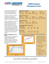
Contact surfaces of mating surfaces should be rigid enough to carry even pressure along the gasket for maximum shielding performance. Maximum enclosure-to-vent shield performance can be achieved by observing the precautions of compatible metals and by spacing the fasteners at no more than 4" on center. Whenever metal ducts are connected to the waveguide air vents on a shielded wall, a dielectric spacing collar is needed to create a nonconducting break on the duct. The purpose of this break is to keep RF currents on the surface of metal ducts from transferring to the shield wall and lowering...
Open the catalog to page 2All ETS Lindgren catalogs and technical brochures
-
 EMP Brochure
8 Pages
-
 E-Vehicle Brochure
8 Pages
-
 Commercial EMC Brochure
4 Pages
-
 Audiometric Brochure
32 Pages
-
 Acoustic Full Line Brochure
16 Pages
-
 5G Brochure
8 Pages
-
 Waveguide Feed-Thru
2 Pages
-
 EMFIELD™ GENERATOR
2 Pages
-
 AUDIOMETRIC SOLUTIONS
32 Pages
-
 ACOUSTIC TESTING SERVICES
4 Pages
-
 S MODEL 8000-025
1 Pages
-
 RF POWER AMPLIFIERS
1 Pages
-
 POSITIONING EQUIPMENT
2 Pages
-
 CHANNEL PARTNER SOLUTIONS
1 Pages
-
 ANECHOIC CHAMBER LIGHTING
1 Pages
-
 CHAMBER ACCESSORIES
2 Pages
-
 Rugged Product Cases
1 Pages
-
 CorpBrochure
24 Pages
-
 Commercial_EMC
4 Pages
-
 Full Line Product Brochure
56 Pages
-
 WirelessCapabilities
20 Pages
-
 FullLineProductBrochure
36 Pages
-
 absorber
32 Pages
-
 Product Brochure
36 Pages
-
 Wireless Capabilities
20 Pages


Archived catalogs
-
 CTIA Authorized Test Lab
2 Pages