

E215 Workholding - Imperial

E215 Workholding - Imperial
- Product Specifications: Detailed descriptions of various hydraulic components such as pressure switches, relief valves, solenoid poppets, and swing clamps. Each product is listed with its model number, specifications, and application details.
- System Components: Information on system components like accumulators, couplers, intensifiers, and rotary unions. This section provides insights into the integration and functionality of these components within hydraulic systems.
- Yellow Pages: A section dedicated to basic hydraulics, system setup, best practices, and safety instructions. It serves as a guide for users to understand and implement hydraulic systems effectively.
- Innovations and Quality Assurance: Enerpac's commitment to innovation and quality is highlighted, with mentions of their ISO 9001 certification and global network of distributors and service centers.
- Swing Clamps: Various models of swing clamps are described, including their compact design, mounting styles, and operational features. The document emphasizes the importance of selecting the right clamp for specific applications.
- Logistics and Global Network: Enerpac's logistics excellence and global distribution network are discussed, ensuring product availability and support worldwide.
- Innovation and Tradition: The catalog highlights Enerpac's tradition of innovation, including the development of new solutions like the Collet-Lok® clamping products and ZW-Class electric pumps.
- WTR-24 Swing Clamp: Operates at pressures between 2000 - 5000 psi with a stroke of 2.50 inches and a force range of 1960 - 5000 lbs. It features a 90° flat rotation and a three-port design for reduced hydraulic connections.
- Work Supports: Available in hydraulic and spring advance models, with force capacities ranging from 1650 to 10,000 lbs and stroke lengths from 0.36 to 0.65 inches. They are designed to minimize deflection and enhance machining accuracy.
- Clamping Sequence: The operation involves pressurizing and depressurizing specific ports (A, B, C) to control the plunger's movement for clamping and unclamping actions.
- Recommended Valving System: Utilizes 4-way 3-position closed center valves, either manual or solenoid operated, with a pressure reducing valve in the 'A' port circuit to prevent cylinder damage.
- Ensure system filtration to maintain reliable operation.
- Do not exceed maximum pressure and flow rates to avoid premature lockup.
- Support force should be at least 150% of the clamping force for optimal performance.
- Features a stainless steel body for corrosion resistance and a fully threaded body for easy installation.
- Multiple mounting configurations are available, including manifold, threaded body, lower flange, and cartridge styles, offering design flexibility.
- Charts included in the document illustrate the relationship between support force and pressure, as well as elastic deflection versus applied load, providing insights into the performance under different conditions.
- Stroke: 0.38 - 0.66 inch
- Pressure: 700 - 5000 psi
- Force: 1650 - 10,000 lbs
- Clamp force: 675-6300 lbs
- Stroke for clamps: 0.73-1.76 inch
- Pressure for clamps: 500-5000 psi
- Do not exceed maximum flow rates to avoid premature lockup.
- Support force should be at least 150% of clamping force.
- Always center load over work support.
- Keep breather port open to a clean, dry location.
- Custom cylinders with longer stroke lengths are available on request.
- Standard and long clamp arms are available, with custom arms possible.
- Contact Enerpac for models with metric threads and BSPP ports.
- Enerpac work supports are available in various mounting styles.
- Threaded work supports can be mounted directly into a fixture.
- Lower flange work supports can be bolted or mounted into a fixture.
- Ensure clamp arm is parallel to cylinder mounting surface within 3°.
- In-line filters and fittings are available.
- Use a flange nut to secure manifold work support.
- Support force and clamping force must be matched.
- Do not exceed maximum flow rates to avoid premature lockup.
- Refer to the “Yellow Pages” of the catalog for safety instructions, basic hydraulic information, and advanced hydraulic technology.
- Threaded Cylinders: Designed for workpiece positioning, holding, and ejecting applications. Available in single and double-acting models, with forces ranging from 380 to 8800 lbs and strokes from 0.24 to 2.03 inches. Operating pressure ranges from 580 to 5000 psi.
- Manifold Cylinders: Compact, fixture-integrated cylinders for space-constrained applications. Forces range from 380 to 6110 lbs, with strokes from 0.28 to 0.98 inches. Operating pressure is between 580 and 5000 psi.
- Installation: Threaded cylinders can be mounted with horizontal brackets for precise workpiece positioning. Manifold cylinders are designed to be screwed directly into a manifold or fixture, eliminating the need for fittings and tubing.
- Usage: Single-acting models are suitable for applications with fewer system restrictions, while double-acting models offer greater control and are ideal for high-cycle applications.
- Use single-acting models for simpler systems with fewer retracting units.
- Opt for double-acting models when precise control and timing are critical.
- Ensure proper installation and torque specifications are followed to maintain system integrity.
- Model numbers, force capacities, stroke lengths, and operating pressures are provided for each cylinder type.
- Dimensions and installation specifications are detailed for each model, ensuring compatibility with specific applications.
- Used for punching, pressing, riveting, and bending applications.
- Available in both double acting and single acting (spring return) configurations.
- Features include manifold mount and plumbed oil connection options, compact design, and integral wiper ring to prevent contamination.
- Models include CDB and CSB series with various clamping capacities and strokes.
- Designed for unobstructed top face machining with independent horizontal and vertical movement.
- Features include compact size, manifold and BSPP porting, and contamination-resistant design.
- Models include ECH and ECM series with specific force and stroke capabilities.
- Used for upgrading mechanical clamping to hydraulic clamping, as well as production pressing and punching.
- Features include high cylinder capacities, spring return operation, and corrosion-resistant design.
- Models include CY and HCS series with various capacities and operating pressures.
- Force range: 2400-60,850 lbs for block cylinders and 870-3900 lbs for pull down clamps.
- Stroke range: .59-2.20 inches for block cylinders and .20-.31 inches for pull down clamps.
- Pressure range: 580-5000 psi for block cylinders and 225-5000 psi for pull down clamps.
- Manifold mounting requires a sealing surface roughness of 63 micro-inches.
- Single-acting cylinders should have a clean, remote termination point for the breather vent.
- Linear cylinder support is required at operating pressures above 2000 psi.
The document outlines the specifications for Enerpac hydraulic cylinders, focusing on the RD and AD series. These cylinders are designed for a maximum operating pressure of 10,000 psi, with force capacities ranging from 3,900 to 24,500 lbs and stroke lengths from 1.11 to 10.28 inches. The document also details the dimensions and options for foot, flange, retainer nut, and clevis eye mountings.
Procedures and Recommendations:
It is crucial to ensure that mounting devices can handle forces in both push and pull directions. The document emphasizes the importance of using appropriate mounting brackets, cylindrical flange nuts, and contact bolts to ensure effective positioning and actuation of the cylinders.
Standards and Norms:
The cylinders adhere to NFPA standards, with specific styles such as ME5 for flange mounts, MS2 for foot mounts, and MP1 for clevis mounts. These standards ensure the cylinders' compatibility and performance in various industrial applications.
Accessories and Options:
Enerpac provides a range of accessories, including spherical contact bolts, jam nuts, and yokes, to enhance the functionality of the cylinders. The document also mentions the availability of seal and repair kits, which include piston, rod, and barrel seals, as well as rod bushings and rear bearing rings.
Performance and Limitations:
The document highlights the performance-tested design features of the cylinders, such as spring-loaded multiple lip vee rings for rod seals and bi-directional sealing cast iron piston rings for piston seals. It also notes that certain models are rated only to 4,000 psi due to mechanical constraints.
Good Practices:
For optimal performance, it is recommended to consult individual product selection pages for specific application and installation criteria. Enerpac offers custom designs to match specific tooling requirements, ensuring flexibility and adaptability in various industrial settings.
- WUD Series: Designed for intermittent duty cycles, suitable for small to medium fixtures. Models include WUD-1100 and WUD-1300 series, offering features like advance/auto-retract and remote valve operation. Pressure rating is 5,000 psi with a flow rate of 25 in³/min.
- WE Series: Submerged electric pumps with options for manual, remote, and solenoid valve controls. Pressure switch specifications include NEMA 1 classification with pressure ranges from 500-7500 psi. The series includes models like WER, WES, and WET, each tailored for specific operational needs.
- ZW Series: High-efficiency pumps designed for harsh environments, featuring a range of configurations for workholding applications. They offer high oil flow, reduced current draw, and are equipped with LCD electrical packages for enhanced control.
- All pumps are equipped with a manifold-mounted gauge for pressure reading, a filter to prevent contamination, and an adjustable pressure switch for pump shut-off control.
- Models are available with different motor voltages and configurations, including options for heat exchangers to support higher duty cycles.
- ZW series pumps provide continuous or momentary pressure and flow, with configurations for single or double-acting circuits.
- Regular maintenance is advised, including oil replacement every 500 working hours and filter changes quarterly or with oil changes.
- Selection of pump models should consider the specific application requirements, including pressure, flow rate, and control type.
- TRK-series Tie Rods: Connects 1 to 8 VP-series valve stations, ensuring leak-free sealing with G1/4" oil connections.
- WM-10 Remote Manifold: Allows remote mounting of VP-series valves with an adjustable relief valve and G1/4" oil connection.
- PB-1 Porting Manifold: Provides three auxiliary pressure lines with G1/4" oil connection, suitable for accessories like pressure gauges.
- Pressure: Up to 5000 psi.
- Flow: 915 in³/min for certain components.
- Mounting: Supports 1-8 VP valve stations.
- VP-series Directional Valves: Zero leakage poppet valves designed for efficiency, suitable for single and double-acting cylinders.
- VSS, VST-series: Solenoid and air piloted directional control valves with zero leakage design.
- VP03-series: Solenoid operated poppet valves for controlling cylinder advance and retract, available in various voltage options.
- VE-series: Spool style solenoid valves for circuits not requiring zero leakage, offering dual flow control and pressure reducing capabilities.
- VMM, VMT-series: Manual directional control valves with near zero leakage, suitable for panel mounting and individual circuit control.
- MB-series Manifolds: Multi-station manifolds for independent control of multiple cylinders, compatible with various valve series.
- BKD-series Valve Mounting Bolt Kits: Ensures correct bolt length for valve stack mounting, includes stud kits for easy installation.
- Use inline check valves like VD1P to prevent pressure drop in holding circuits.
- Ensure proper torque and stud length for mounting components.
- Pressure on the return side should not exceed 250 psi.
- These valves are ideal for applications requiring independent control of multiple cylinders. They are available in various configurations such as 2-way, 3-way, and 4-way with different positions and flow paths.
- Specifications include a pressure range of 0-10,000 psi, maximum flow of 920 in³/min, and voltage options of 24 VDC, 115 VAC, and 230 VAC.
- Accessory valves like VS-11 relief valve and VS-51/61 pilot-operated check valves can be added for enhanced functionality.
- These valves are used for controlling single-acting and double-acting cylinders, available in 3-way and 4-way configurations.
- They offer options for non-locking, closed center, locking center, and tandem center positions to suit different hydraulic circuit requirements.
- Pressure range is 0-10,000 psi with a maximum flow of 1040 in³/min.
- Sequence valves control the flow to secondary hydraulic circuits based on pressure settings, ensuring operations like work support before applying swing cylinders.
- Pressure settings range from 200-5000 psi, with models like V-2000, MVPC-5, MVPM-5, and WVP-5 offering different flow capacities and mounting options.
- These valves ensure load holding and remote unlocking of cylinders, featuring a pilot ratio of 7:1 and a maximum flow of 10 gpm.
- They include built-in accumulators to maintain system pressure and are available in manifold mount configurations.
- Valves are designed for both pump and remote mounting, providing flexibility in system design.
- Locking options are available for applications requiring positive load holding.
- Various accessory and bolt kits are available to customize and enhance valve functionality.
- Seal Material: Buna-N for V-72 and Viton for VFC-series.
- Pressure Ratings: Various components have pressure ratings up to 10,000 psi.
- Flow Rates: Maximum oil flow rates are specified for different models, such as 427 in3/min for PRV-series and 10 gpm for VFC-series.
- Retraction of cylinders can be automated without operator intervention.
- Manifold mounting requires specific surface preparation as per Enerpac guidelines.
- Pressure Reducing Valves (PRV-series): These valves maintain constant pressure in secondary circuits and include a check valve to prevent pressure drop.
- Flow Control Valves (VFC-series): Designed for precise oil flow control with a poppet valve design for zero leakage.
- Accessory Valves: Used for automating clamp cycles and preventing pressure loss, featuring NPT or SAE porting for leak prevention.
- Hydraulic systems requiring precise pressure control and flow regulation.
- Use in conjunction with Enerpac WE-series workholding pumps to protect components from high flow rates.
- Air valves for controlling air-operated hydraulic units, enhancing productivity and efficiency.
- Valves can be manifold mounted or plumbed with tubing.
- Specific models like PRV-3 and PRV-4 are designed for remote mounting.
- Accumulators: Used for energy storage, circuit pulsation dampening, and thermal expansion compensation.
- Air Valves: Include manual and solenoid-operated options for controlling air supply to hydraulic units.
- Designed for automated coupling of hydraulic circuits on palletized systems, eliminating the need for direct operator intervention.
- Features include sensing feedback for automated applications, flexible mounting options, and air blow-off nozzles to prevent contamination.
- Available in 2 or 4 port models with a maximum oil flow of 4.3 GPM.
- Includes an automatic coupler control box with pre-programmed safety features.
- Used to transfer pressurized fluid from a stationary supply line to a rotating device, suitable for workholding or clamping devices.
- Features high rotation per minute, low starting torque, and internal oil bearings for increased lifetime.
- Available in models with different passages and pressure ranges, with a maximum operating speed of 100 RPM.
- Increase output pressure when hydraulic pressure from an existing power source is limited.
- Features internal bypass valving, a range of intensification ratios, and a compact design.
- Models available with maximum pressures up to 10,000 psi and various intensification ratios.
- Provides wireless communication between fixture circuits and machine control using radio communication.
- Operates on a 2.4 GHz frequency band with frequency hopping for signal stability.
- Includes SEND units with replaceable batteries and sealed to IP-67 for protection.
- Compatible with Modbus RTU RS485, Ethernet IP, and Modbus TCP/IP protocols.
- Ensure accurate positioning of pallet and base stations for leakage-free connections.
- Do not exceed maximum flow and pressure limits to avoid damage.
- Use high-pressure filters to prevent contamination of valves and cylinders.
- Consult Enerpac for support on proper application, clamp force, pressures, and timing.
- IP Rating: SafeLink units have an IP67 rating, ensuring protection against dust and water.
- Communication Protocols: Supports Modbus RTU RS485 and Ethernet TCP/IP for data transmission.
- Radio Frequency: Operates at 2.4 GHz.
- Pressure Switch Range: PSCK-8 (1450–5000 psi), PSCK-9 (290–3045 psi).
- SLR-1 Receive Unit: Interfaces with machine control, providing 24 VDC outputs and Modbus RTU RS485 communication.
- SLS-1, SLS-2, SLS-3 Send Units: Transmit data from fixtures to the receive unit.
- SLEM-1 Expansion Module: Adds additional terminal stations for increased capacity.
- SLEB-1 Ethernet Bridge: Converts Modbus RTU to Ethernet IP or Modbus TCP/IP.
- SafeLink monitors fixture pressure and clamp position in real-time, ensuring correct operation during machining processes.
- If a pressure deficiency is detected, the system interrupts the signal to the machine control, preventing potential damage.
- The system can handle up to 56 send units monitored by a single receive unit.
- The send unit is powered by a 3.6 VDC lithium battery with a projected life of 3 years.
- The receive unit requires a 24 VDC power supply, typically sourced from the machine control.
- Custom installation services are available through Enerpac's CNC control specialists.
- Ensure machine control is configured to respond to SafeLink protocols for effective operation.
- Regularly check battery life and replace as necessary to maintain system functionality.
The document provides detailed specifications for various hydraulic components, including gauges, hoses, couplers, and fittings. It lists pressure ratings, dimensions, and model numbers for each component, emphasizing the importance of not exceeding maximum pressure limits.
Procedures and Recommendations:
The document recommends using gauge snubbers or needle valves for high cycle applications and advises against keeping gauges under permanent pressure. It suggests using shut-off valves and provides guidelines for basic system setup, referring to the 'Yellow Pages' section for more information.
Standards and Norms:
Enerpac components are designed to meet specific pressure ratings, with fittings and manifolds allowing for flexible and leak-free connections. The document highlights the importance of using genuine Enerpac products to ensure optimal performance and longevity.
Key Components and Options:
- Gauges: Various models with different pressure ratings and dimensions.
- Hoses and Tubing: High-pressure hydraulic hoses with protective coatings and steel tubing for permanent installations.
- Couplers: Quick disconnect designs for easy connection and disconnection.
- Filters: High-pressure filters to keep hydraulic systems clean and prevent damage.
Important Notes:
The document stresses the importance of not exceeding maximum pressure and regularly inspecting hoses and tubing. It also advises using anaerobic thread sealers or Teflon paste for sealing NPT threads.
Additional Information:
The 'Yellow Pages' section provides further guidance on hydraulic system setups, safety instructions, and conversion factors. Enerpac's warranty statement and quality certifications are also mentioned, ensuring compliance with management and product development standards.
Enerpac has achieved the ISO 9001 quality rating, demonstrating its commitment to excellence. Electrical components in Enerpac products are UL approved where possible, and certain electric pump assemblies meet Canadian Standards Association requirements. Hydraulic components are designed for safe use at a maximum pressure of 350 bar/5,000 psi. Enerpac products also comply with the EMC Directive 89/336/EEC for electromagnetic compatibility and carry CE marking for conformity with European Community Directives.
Hydraulic clamping enhances machine shop efficiency by reducing setup time and minimizing manual clamping injuries. Operators should follow safety practices, such as preventing inadvertent activation of control units and maintaining a safe distance from clamping elements. Enerpac provides safety instructions with each product, emphasizing the importance of using genuine Enerpac hydraulic oil and adhering to operational limits.
Hydraulic systems operate based on principles like Pascal's Law, where pressure applied to a confined liquid is transmitted equally in all directions. The force generated by a hydraulic cylinder is determined by the pressure and the cylinder's effective area. Proper system setup involves selecting the right components, such as control valves, to ensure uniform operation.
Building an effective workholding system involves selecting appropriate cylinders based on workpiece shape and machining processes. Enerpac offers a range of cylinders for positioning, clamping, and supporting workpieces. The power source should match system requirements, and components must be connected correctly using hoses, fittings, and gauges.
Swing cylinders and work supports are crucial for fixturing applications, allowing for unrestricted loading and unloading of workpieces. Proper selection of clamping force and support force is essential to prevent workpiece deflection and ensure quality. The use of sequence valves and flow control valves is recommended to manage oil flow rates and ensure safe operation.
- A hydraulic clamping mechanism uses hydraulic media to apply force and secure a workpiece. The system can reach pressures up to 5000 psi (350 bar), allowing significant clamping forces with compact cylinders.
- Key components include clamping plungers, pressure pistons, and hydraulic mediums.
2. Assembly of Hydraulic Clamping Devices
- Locating and supporting workpieces involves positioning them correctly to limit their degrees of freedom, ensuring they are held securely for machining.
- Degrees of freedom are reduced by introducing reference planes, with three main techniques: semi-constrained, constrained, and fully-constrained workpieces.
- Avoid over-location to prevent machining errors and ensure correct placement of workpieces.
3. Clamping Techniques
- Clamping secures a positioned workpiece for machining, involving force transmission through the device.
- Mechanical and hydraulic clamping methods are used, with hydraulic clamping adjusting to changes while maintaining constant force.
- Design guidelines suggest keeping clamping forces away from critical tolerance zones and minimizing deformation.
4. Supporting the Workpiece
- Support ensures force transmission and prevents deformation during machining.
- Options for supporting bent workpieces include using self-adjusting spherical surfaces to accommodate deformations.
- Clamping force should be applied to solid bearing surfaces to prevent movement during machining.
5. Cutting Technology
- Cutting operations include boring, drilling, end milling, and face milling, with hydraulic workholding commonly used in milling.
- Cutting force calculations involve spindle horsepower and material removal rates, with examples provided for face milling.
This section provides formulas and calculations for determining tool RPM, material removal rate (MRR), and spindle horsepower. For example, Tool RPM is calculated using the formula: Tool RPM = SFM / (Diameter x 0.2618). The MRR is calculated as: MRR = Width of cut x Depth of cut x Feed per tooth x Number of teeth x RPM. Spindle horsepower is determined using unit horsepower values from a table, specifically for aluminum with a dull tool.
Cutting force is calculated using spindle horsepower and efficiency factors. Safety factors are applied for rigid and elastic clamping, with considerations for friction coefficients, especially when using hydraulic systems.
Tables provide unit power requirements for various materials and hardness levels, both in imperial and metric systems. These are essential for determining the power needed for turning, drilling, and milling operations.
This section includes conversion factors for pressure, weight, temperature, volume, and other measurements, facilitating the translation between imperial and metric systems.
Recommendations for hydraulic workholding systems include using double-acting cylinders for critical cycle times, selecting appropriate hydraulic pumps, and ensuring proper breather vent placement to avoid contamination. Manifold mounting is advised to save space and simplify installation.
Descriptions of various hydraulic components such as pumps, valves, and cylinders are provided, along with examples and their applications in hydraulic systems.
- Pressure Gauges and Couplers: Various types of hydraulic couplers are discussed, including single, double, and four-passage rotary couplers.
- Accumulators: Gas charged and spring-loaded accumulators are explained for maintaining system pressure.
- Heat Exchangers and Filters: Essential for maintaining system temperature and cleanliness.
- Directional Control Valves: These include 3-way and 4-way valves, essential for controlling the flow direction in single and double-acting cylinders.
- Pressure Control Valves: Types include relief valves, sequence valves, pressure reducing valves, and pressure limiting valves, each serving specific functions in managing system pressure.
- Flow Control Valves: These regulate the speed of hydraulic components, with features like free flow reverse checks for efficient operation.
- Hydraulic Workholding: Enhances machining cycle efficiency through rapid positioning, clamping, and release of workpieces.
- Palletized Fixtures: Discusses the challenges and solutions in using palletized fixtures for increased productivity.
- Collet-Lok® Technology: A key innovation that eliminates the need for live hydraulics during machining, using mechanical locks to maintain clamping force.
- Hydraulic Clamping and Locking: Describes the step-by-step process of using Collet-Lok® cylinders for secure clamping without continuous hydraulic pressure.
Catalog excerpts

POWERFUL SOLUTIONS. GLOBAL FORCE.
Open the catalog to page 1
Yellow Pages Refer to the “Yellow Pages” of this catalog for: All information in this catalog can be changed due to product improvements without prior notice. © Copyright 2013, Actuant Corp. All rights reserved. Any copying or other use of material in this catalog (text, illustrations, drawings, photos) without express written consent is prohibited. • Safety instructions • Basic hydraulic information • Advanced hydraulic technology • FMS (Flexible Machining Systems) technology • Conversion charts and hydraulic symbols
Open the catalog to page 2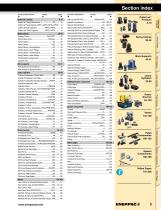
Product index Yellow Pages System Components Pallet Components Power Sources Linear Cylinders Work Supports Collet Lok® Products 8-19 Swing Clamps Collet-Lok® Products Section index
Open the catalog to page 3
The World Class Brand A complete range of quality Workholding products for all production applications, with local availability and after sale service anywhere in the world….this is what makes Enerpac a global leader in hydraulic Workholding. Across every continent, Enerpac’s network of authorized distributors and service centers provide sales and support of products designed to enhance productivity and performance, while making the work place safer. Always at the leading edge of technology, Enerpac continues to develop its range of time and cost saving products, utilizing modern engineered materials...
Open the catalog to page 4
Enerpac Workholding Value Proposition • Expert Design • Highly Reliable • Service Excellence • Worldwide Experience • Application Support • Availability • Quality • Value • Innovative Products • Systems Solutions Total Quality Our products are tested to the most exacting standards. These high standards guarantee the quality, price and performance requirements of the markets we serve around the globe. Global Network Enerpac has an extensive network of authorized distributors and service centers located in more than 90 countries worldwide. You can rely on Enerpac for the products and technical...
Open the catalog to page 5
A Guide to Your New Enerpac Workholding Catalog The New Enerpac Workholding catalog; ... helps you design more efficient workholding fixtures, ... is a global resource of workholding solutions. This catalog is set-up in two main sections: 1 Imperial hydraulic product data section All Enerpac hydraulic workholding products shown with imperial based specifications and dimensions. 2 Yellow Pages section Your guide to safety, basic hydraulics and application suggestions. Selecting the right product for your application: 1. Select your main product category from the main index on page 3. This index...
Open the catalog to page 6
Range overview Swing Clamps series Swing cylinder range overview Upper ange swing clamps Lower ange swing clamps Threaded body swing clamps Cartridge model swing clamps Clamp arms Pivoting T-arms Upreach clamp arms Swing clamps Swing clamps Three-position swing clamps Swing Clamps Enerpac’s complete line of swing clamps provides maximum clamping force in the smallest possible package. With several mounting and operation styles available, Enerpac can t any clamping need you can think of. Our unique patented clamp arm design is an industry exclusive, and makes Enerpac’s swing cylinder line more...
Open the catalog to page 7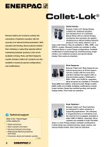
Collet-Lok® Swing Clamps Enerpac Collet-Lok® products combine the automation of hydraulic actuation with the security of an internal locking mechanism. After actuation and locking, these products maintain their clamping or supporting capacity without maintaining hydraulic pressure in the circuit. Available in Swing, Push, and Work Supports Enerpac Collet-Lok® Swing Clamps combine the rotational actuation and clamping force of a hydraulic Swing Clamp with an internal locking mechanism that maintains the applied clamping force without holding hydraulic pressure in the clamp. Ideal for use in large-scale...
Open the catalog to page 8
Collet-Lok® swing cylinder range overview 10-11 Collet-Lok® Swing clamps WPTL 12-15 Collet-Lok® Push cylinders WPTC 18-19 §^
Open the catalog to page 9
Application & selection Shown: WPTR-100V and WPFR-100V Collet-Lok® products Hydraulic actuation with mechanical lock • Collet-Lok® technology combines hydraulic actuation for clamping or supporting with an internal locking collet • lamp bodies are available in either threaded mount or C flange mount • lange mount units feature both tubing ports and bottom F manifold ports • lange top manifold ports available as a special F • VITON seals are standard Enerpac Collet-Lok® cylinders are designed to mechanically hold the workpiece after hydraulic pressure is removed. Clamping capacities range from...
Open the catalog to page 10
Force: 1000 - 8500 lbs Collet-Lok® Products C ollet-Lok® technology from Enerpac combines hydraulic actuation with mechanical locking to provide the automation and control of hydraulics and the long term security of a mechanical lock. Available in Swing Clamps, Push Cylinders and Work Supports, Collet-Lok® is a unique solution that is well suited to today's demanding manufacturing environment. Stroke: .94 - 1.65 inch Pressure: 1400 - 5000 psi Collet-Lok® Clamping and Unclamping Cycle Clamping 90˚ Rotation + Clamp Lock Unlock Unclamp + 90˚ Rotation After being in the machine the pallet returns...
Open the catalog to page 11
Swing cylinders - Collet-Lok® design Shown: WPTR-100V, WPFR-100V Collet-Lok® products Ideal when live hydraulics are not available • Double acting Collet-Lok® action allows fully automated operation • dditional level of safety since live hydraulics are not required to maintain A clamping force • ollet-Lok® swing cylinders can be mounted by the flange or threaded into the C fixture. Flanged models have manifold ports and tubing ports. • iton seals are standard V Left turning Enerpac Collet-Lok® cylinders are designed to mechanically hold the workpiece after hydraulic pressure is removed. Clamping...
Open the catalog to page 12
WP series Installation dimensions in inches Mounting thread J mm M10 x 1,50 Mounting flange Sold separately 87 ▸ Mounting nut Sold separately 86 ▸ Work Supports Vérins de bridage pivotants Fixture hole 1 90° Rotation and clamp 2 Locks system With standard clamp arm. Custom Options Available Intermediate capacities Different flange locations Linear Cylinders Power Sources Pallet Components Flexible Machining Systems Clamp arms Collet-Lok® work supports System Components Swing Clamps Collet-Lok® Products Clamping Fixture hole force1) lbs ø D3 t Lower flange Sequence valves Right turning models...
Open the catalog to page 13All ENERPAC catalogs and technical brochures
 HTM, LPHT, MHT Series
1 Page
 SCTB-Series Toolbox Sets
1 Page
 Bolting Tools E415
136 Pages
 INDUSTRIAL TOOLS E330a
428 Pages
 ZE2-SERIES ELECTRIC PUMPS
2 Pages
 ETR-Series Trolley Systems
4 Pages
 Skidding Systems HSK-Series
2 Pages
 Hydraulic Presses
10 Pages
 Inline Filters
1 Page
 Manifolds
3 Pages
 Load Skates
2 Pages
 Hydraulic and Mechanical Pullers
14 Pages
 PA-Series Air Pumps
1 Page
 Machine Lifts SOH series
1 Page
 PR-Series Wheeled Jacks
2 Pages
 ZA4-Series Air Pumps
2 Pages
 Directional Control Valves
6 Pages
 Workholding Pumps
40 Pages
 JS-Series Jack-Up Systems
8 Pages
 LW-series
1 Page
 Hydraulic Pumps and Power Units
50 Pages
 MP series
1 Page
 Pressure Intensifiers
2 Pages
 Coupler Packages
13 Pages
 SFP-Series, Split-Flow Pumps
2 Pages
 MS-Series
4 Pages
 TM LH Series
1 Page
 DuroTech™-Series
4 Pages
 High Tonnage Cylinder
20 Pages
 E328a
E328a288 Pages
 E329 Industrial Tools Catalog
294 Pages
 A, C-Series
1 Page
 STB-Series
2 Pages
 E328e
E328e280 Pages
 E413 Bolting Tools
88 Pages
 E413e Bolting Tools
88 Pages
 E327e Industrial Tools
268 Pages
 WCC World Class Collection
16 Pages
 Tools for Bridge Maintenance
2 Pages
 E327 Industrial Tools
258 Pages
 Bolting Solutions
88 Pages
 SBL-1100 Hydraulic Gantry
4 Pages
 Collet-Lok® Product Family
2 Pages
 TQ-700 Electric Wrench Pump
4 Pages
 XC-SerieS CORDLESS PuMPS
2 Pages
 E501 Mechanical Actuators
92 Pages
 Integrated Solutions Capability
28 Pages
 E326e Industrial Tools
260 Pages


