

Low-Voltage Line

Low-Voltage Line
ENERLUX specializes in energy optimization solutions, focusing on capacitors and automatic power-factor correction systems for low and medium voltage. Their products are known for continuous research, professionalism, experience, and ISO 9001 certified quality.
Correct sizing of electrical installations and equipment is crucial for reducing waste and optimizing energy use, minimizing costs. Power-factor correction is key for energy savings by limiting energy losses, voltage drops, and reducing installation costs, while avoiding penalties from energy supply contracts.
Electrical equipment requires active power (P) and reactive power (Q) for operation. The power factor, indicated as “cosφ”, is the ratio of active power to apparent power. A low power factor increases apparent power demand, leading to higher voltage drops and losses.
Power-factor correction can be implemented in various ways:
- Distributed Correction: Suitable for constant loads like transformers and large motors, where capacitors are connected in parallel near the load.
- Centralized Correction: Typically involves a central capacitor bank for multiple loads.
- Mixed and Group Correction: Involves combinations of distributed and centralized methods.
This method is cost-effective as it allows the load and correction system to operate simultaneously, avoiding additional switching and protection devices.
Power factor correction is essential for optimizing electrical systems, reducing losses, and improving efficiency. It can be achieved through various methods depending on the application and needs, including individual, centralized, mixed, and group power factor correction.
This method is suitable for constant load services like transformers and large motors. It involves connecting capacitors in parallel near the load to correct the power factor. The benefits include economic installation and operation, as it reduces voltage drops and losses.
Ideal for installations with discontinuous utilization times, this method is implemented near the transformation box or main panel. It uses capacitor banks controlled by automatic regulators, offering flexibility and economic advantages, especially in large industrial complexes.
For centralized correction, knowing the initial and desired power factor (cosφ), the reactive power can be calculated using the active power drawn, the number of working hours per day, and the number of working days.
Example calculations demonstrate the capacitive power needed for installations with specific power factors and loads, illustrating the process of achieving desired power factor levels.
For three-phase asynchronous motors, the capacitor's power should not exceed 90% of the motor's reactive power. For transformers, especially those operating with no load, capacitors compensate for the magnetizing current.
Electrical installations can be affected by interference from distribution networks and non-linear loads, leading to waveform distortions. These distortions can increase losses and cause resonance issues in electrical equipment.
This document discusses the origins and effects of current and voltage distortions in electrical systems, particularly focusing on non-linear loads, arc furnaces, and large welding installations.
- Current Distortions: Caused by non-linear loads like semiconductor rectifiers, arc furnaces, and large welding installations.
- Voltage Distortions: Linked to saturation phenomena in transformers and deformation of generator voltage waves.
Distortions lead to increased losses, overheating of conductors due to the Joule effect, and additional losses in magnetic circuits.
For transformers operating at no load or with limited load, it is necessary to compensate the absorbed power by connecting capacitors in parallel.
Harmonics can cause current overloads in capacitors and induce losses and mechanical vibrations in transformers and motors.
It is advised against using only capacitors for power factor correction in the presence of distortions due to the risk of resonance.
Power factor correction equipment should include devices for operation, protection, and control.
The document discusses the use of contactors in installations, emphasizing the importance of proper sizing based on rated current, transient currents during capacitor operations, and operation frequency.
Protection devices include fuses, circuit breakers, and thermal relays.
Proper equipment sizing requires consideration of climatic and environmental conditions, including temperature, humidity, and installation location.
Enerlux's capacitors for low-voltage applications are self-healing, made from metalized polypropylene film, and offer improved performance.
The document explains that low power factor loads demand more apparent power, leading to voltage drops and losses.
Low power factor loads require more apparent power from the network compared to high power factor loads, leading to increased voltage drops and losses.
Capacitors in metallized polypropylene film are equipped with protection mechanisms to disconnect the power supply at the end of their life or in case of excessive overvoltage.
Capacitors must be installed considering specific operating conditions to avoid performance alterations and lifespan reduction.
Capacitors are often rated for higher voltages than the network to prevent dielectric damage from overvoltages.
The working temperature is crucial for proper capacitor function and lifespan.
The document outlines the classification of capacitors according to Italian CEI EN 60831-1/2 and international IEC 831-1/2 standards.
Capacitors with a nominal voltage higher than the network voltage are often used to prevent dielectric breakdown due to overvoltages.
After disconnection from the network, the residual voltage across a capacitor must drop below 75 V within 3 minutes to ensure safety during maintenance.
Proper functioning and lifespan of capacitors depend on operating within specified temperature ranges.
Capacitors and related equipment should only be used for power factor correction in AC systems, adhering to specified service conditions.
Enerlux emphasizes environmental protection, producing low-voltage power-factor correction products with non-toxic components.
Capacitors should be stored in original packaging in dry, covered areas, and handled with care to avoid mechanical stress.
When dealing with harmonics, it is crucial to consider voltage increases at capacitor terminals and potential resonances.
Enerlux provides guidelines for selecting suitable capacitors based on network conditions.
The document outlines the technical specifications for PRT and DPRT series capacitors.
The PRT series capacitors are self-healing and consist of three single-phase elements made of metallized polypropylene film.
Installation requires fixing the M12 spigot of the capacitor.
The document lists various models of PRT capacitors with different ratings, dimensions, and specifications.
The capacitors conform to CEI EN 60831-1/2 and IEC 60831-1/2 standards.
The document provides detailed specifications for three-phase capacitors of the UTF and FT series.
The capacitors are housed in robust steel casings painted with epoxy resins.
Installation requires using specific fixing slots on the casing brackets.
The capacitors operate at voltages ranging from 230V to 550V and frequencies of 50 Hz.
The capacitors comply with CEI EN 60831-1/2 and IEC 60831-1/2 standards.
The tables provide specific models with their respective power ratings (kvar), voltage ratings, and dimensions.
The document outlines the specifications for CTF and CTFX series modular units designed for networks with harmonic distortion.
Before installation, it is crucial to check the harmonic load of the power supply network.
The units comply with CEI EN 60439-1, IEC 439-1, and CEI EN 60831-1/2 standards.
For optimal performance, ensure the installation is in a vertical position on the bar system.
The document provides detailed technical specifications, including rated voltage (400V), frequency (50Hz), temperature class, dielectric losses, and insulation level.
RA-type reactors are designed for high harmonic loads and are tuned to capacitors.
The document outlines the specifications for the ERA and ERAF series of automatic power-factor correction equipment.
- Three-pole fast-tripping disconnecting switch interlocked with the door.
- Sets of three fuses (type DIII or NH00 curve gG) with high breaking capacity for capacitor bank protection.
- Three-pole contactors for battery connection, designed to limit current peaks.
- PRT type capacitors and flameproof internal connecting cables (type N07VK).
- Copper bars (30x5 mm) and an electronic regulator for automatic battery connection and cosφ control.
- Forced ventilation system with thermostat-operated fans.
Before installation, it is crucial to check the harmonic load of the power supply network and adhere to the service conditions.
- Rated voltage: 400 - 550 V
- Rated frequency: 50 Hz (60 Hz on request)
- Short-circuit current: 30 kA for 1 second
- Installation: Indoor, freestanding, in dust-free environments
- Protection degree: IP40/IP54 (closed), IP20 (open)
- Reference standards: CEI EN 60439-1, IEC 439-1 for equipment; CEI EN 60831-1/2, IEC 831-1/2 for capacitors
The ERAF series is designed for networks with harmonic distortion.
1. Harmonic Distortion: Current distortion allowed in continuous operation is 30% at 250 Hz and 15% at 350 Hz. Maximum harmonic distortion in voltage permitted in the network (THD%) is 5%.
- Metal cabinet with cooling fins, corrosion-protected and epoxy powder painted.
- General three-pole switch with quick release, locked with the door.
- NH00 type fuses for capacitor protection.
- Tripolar contactors for battery insertion with advanced resistance limitation contacts.
- Oversized dielectric capacitors of the "dry" PRT type.
- Flame-retardant internal connection cables.
- Copper bars 30x5 mm.
- Electronic regulator for automatic battery engagement and cosφ control.
- Forced ventilation system with thermostatically controlled fans.
- Blocking reactors with high-quality magnetic core.
- Check the harmonic load of the power supply network before installation.
- Ensure correct tightening of terminals and bolts.
- Follow installation, connection, and maintenance instructions.
- Rated Voltage: 400 V
- Rated Frequency: 50 Hz (60 Hz on request)
- Tolerance on Capacitance: -5% to +10%
- Temperature Class: -25°C to +50°C
- Installation: Indoor, dust-free environments, vertical setup.
- Short-circuit Current: 30 kA for 1 second.
- Degree of Protection: IP40/IP54 (closed), IP20 (open).
- Reference Standards: CEI EN 60439-1, IEC 439-1 for equipment; CEI EN 60831-1/2, IEC 831-1/2 for capacitors.
- Automatic power factor regulator with microprocessor management for 6-12 steps.
- Features THD I% control, RS232 or RS485 serial connector.
- Measures voltage, current, power factor, internal temperature, and harmonic distortion using FFT.
- Capable of managing capacitor steps to reduce switchings and ensure uniform usage.
- Provides alarm monitoring and records switchings for wear verification.
- True RMS measurement of voltage and current.
- Reactive power measurement.
- Power factor adjustment.
- THD I% and resonance frequency alarm settings.
- Records maximum values of power, voltage, current, and temperature.
- Allows setting of external transformer parameters.
- Batteries can be set in "FIX" mode for constant protection.
- Monitors micro-interruptions and voltage dips, protecting capacitors.
- All settings and information available via RS232 or RS485 connectors.
Catalog excerpts

Linea Bassa Tensione IJ Ligne Basse Tensior WH
Open the catalog to page 1
ENERLUX NASCE da un’idea PROGETTA con sapiente cura SVILUPPA nel rispetto per l’uomo e l’ambiente OTTIMIZZA l’utilizzo dell’energia ENERLUX ORIGINATES in an idea DESIGNS with knowing care DEVELOPS while being people and environment friendly OPTIMIZES the use of energy ENERLUX NAÎT d’une idée PROJETTE attentivement DÉVELOPPE dans le respect de l’homme et de l’environnement OPTIMISE l’utilisation de l’énergie ENERLUX produce un’ampia gamma di condensatori e sistemi automatici di rifasamento industriale in bassa e media tensione. Ricerca continua, professionalità, esperienza, qualità certificata...
Open the catalog to page 2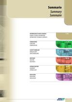
Sommario Summary Sommaire INFORMAZIONI TECNICHE GENERALI GENERAL TECHNICAL INFORMATION INFORMATIONS TECHNIQUES GÉNÉRALES 2-20 CONDENSATORI CAPACITORS CONDENSATEURS 21-34 CASSETTI MODULARI MODULAR UNITS UNITÉS MODULAIRES 35-42 REATTANZE REACTORS REACTANCES 43-45 APPARECCHIATURE EQUIPMENT APPAREILLAGES 46-61 REGOLATORI REGULATORS REGULATEURS 62-65
Open the catalog to page 3
Informazioni tecniche generali General technical information Informations techniques générales PREMESSA INTRODUCTION AVANT-PROPOS Il corretto dimensionamento degli impianti elettrici e delle apparecchiature utilizzatrici consente una riduzione degli sprechi ma soprattutto una razionale utilizzazione dell’energia elettrica, con conseguente ottimizzazione dei costi ad essa correlati. Una prerogativa fondamentale per minimizzare la spesa relativa all’acquisto dell’energia è la riduzione delle perdite a partire dalla generazione fino alla distribuzione ed utilizzazione. Il rifasamento è una delle...
Open the catalog to page 4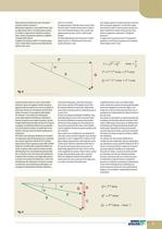
dovuta alla parte induttiva del carico) alla quale è associata la potenza reattiva Q. Nella potenza apparente S viene quindi tenuto conto sia dalla potenza attiva P che della potenza reattiva Q. La figura A rappresenta la relazione tra potenza attiva, reattiva ed apparente mediante il cosiddetto “triangolo delle potenze”. Il rapporto fra la potenza attiva P e la potenza apparente S è detto fattore di potenza ed è abitualmente indicato come “cosφ”. power Q is associated. The apparent power S therefore takes account of both the active power P and the reactive power Q. Figure A shows the relationship...
Open the catalog to page 5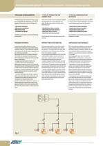
Informazioni tecniche generali • General technical information • Informations techniques générales TIPOLOGIE DI RIFASAMENTO TYPES OF POWER FACTOR CORRECTION TYPES DE COMPENSATION DE PHASE Il rifasamento può essere realizzato in diverse modalità a seconda delle varie applicazioni e necessità; le tipologie di rifasamento si possono distinguere in: • Rifasamento distribuito • Rifasamento centralizzato • Rifasamento misto • Rifasamento per gruppi Power factor correction can be accomplished in different ways depending on the various applications and needs. The types of power factor correction can...
Open the catalog to page 6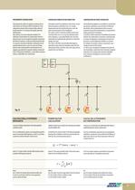
RIFASAMENTO CENTRALIZZATO CENTRALIZED POWER FACTOR CORRECTION COMPENSATION DE PHASE CENTRALISÉE Particolarmente adatto in impianti caratterizzati da varie utenze con tempi di utilizzo discontinui; viene solitamente attuato nelle vicinanze della cabina di trasformazione o in vicinanza del quadro generale dell’impianto. Tale sistema, che viene realizzato mediante l’installazione di più batterie di condensatori inserite o disinserite per mezzo di appositi regolatori automatici del fattore di potenza, risulta particolarmente flessibile in quanto consente di adattarsi continuamente ed autonomamente...
Open the catalog to page 7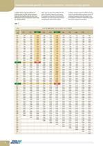
Informazioni tecniche generali • General technical information • Informations techniques générales La Tabella 1 fornisce i valori del coefficiente “K” mediante il quale è possibile ottenere la potenza reattiva QC nota la potenza attiva del carico, il cosφ dell’impianto in assenza di rifasamento e scelto il cosφ’ che si desidera ottenere. tab. 1 6 Table 1 gives the values of the coefficient “K” with which it is possible to obtain the reactive power QC, knowing the active power of the load and the installation’s cosφ with no power factor correction and choosing the cosφ’ you want to obtain. Le...
Open the catalog to page 8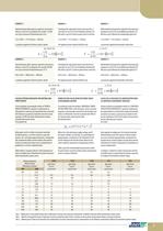
Determinazione della potenza capacitiva necessaria a rifasare a cosj'0,92 un impianto che assorbe 132 kW, con cosj in assenza di rifasamento pari a 0,6. La potenza apparente richiesta variera quindi Calculating the capacitative power necessary for p.f. correction to cos]'0.92 of an installation drawing 132 kW, with a cos] of 0.6 with no power factor correction. The apparent power required will then vary Détermination de la puissance capacitive nécessaire pour compenser à cos]'0,92 une installation qui absorbe 132 kW, avec cos] en l'absence de compensation égala 0,6. La puissance apparente demandée...
Open the catalog to page 9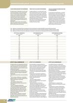
Informazioni tecniche generali • General technical information • Informations techniques générales CALCOLO POTENZA RIFASANTE PER TRASFORMATORI POWER FACTOR CALCULATION FOR TRANSFORMERS Per quanto concerne i trasformatori, nei casi in cui gli stessi possano funzionare a vuoto (cicli discontinui), esiste la necessità di rifasare la potenza assorbita a vuoto o con carico limitato inserendo in parallelo al trasformatore una batteria di condensatori; i condensatori hanno lo scopo di compensare la corrente magnetizzante del trasformatore che serve a generare il campo magnetico necessario per il suo...
Open the catalog to page 10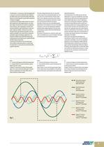
I trasformatori e i cavi possono subire danneggiamenti a causa di un eccessivo riscaldamento dei conduttori per effetto Joule e per l'incremento delle perdite addi- zionali nei circuiti magnetici causato dalle componenti La tensione di rete distorta dalle correnti non sinusoi- dali assorbite dai carichi inquinanti può, a sua volta, dare origine ad armoniche di corrente in componenti di per sé lineari, come condensatori e resistori ed in macchine elettriche, quali trasformatori e motori nei quali si inducono perdite e vibrazioni meccaniche. Secondo Fourier, ogni fenomeno periodico non sinu- soidale...
Open the catalog to page 11All Enerlux catalogs and technical brochures
 Regulators
4 Pages
 Medium and High Voltage Line
60 Pages
Archived catalogs
 AUTOMATIC POWER-FACTOR EQUIPMENT
23 Pages
 THREE-PHASE CAPACITORS
21 Pages
 MODULAR RACK
11 Pages
- Ceramic capacitor
- Power capacitor
- Film capacitor
- Cylindrical capacitor
- Cylindrical fuse
- Filter capacitor
- High-voltage fuse
- Compensator
- Limiting fuse
- Single-phase capacitor
- Harmonic filter reactor
- Encapsulated capacitor
- Three-phase harmonic filter reactor
- Power factor controller
- Digital power factor controller
- PFC capacitor
- Pole-mounted capacitor