
- Catalogs
- EGE-Elektronik Spezial-Sensoren GmbH
- Flow controllers / Air flow controllers

- Products
- Catalogs
- News & Trends
- Exhibitions
Flow controllers / Air flow controllers

Flow controllers / Air flow controllers
This document from EGE-Elektronik Spezial-Sensoren GmbH provides comprehensive technical information on flow sensors, amplifiers, and compact models used in automation. It includes specifications, applications, installation guidelines, and material considerations for various sensor series.
Flow sensors operate on the thermodynamic principle, using temperature differences to determine flow states. They are suitable for both liquid and gaseous media, valued for reliability due to the absence of moving parts.
Flow sensors are used in monitoring cooling systems, run-dry protection for pumps, filter monitoring, and handling aggressive media in cleaning processes and laboratories.
Probes are made from stainless steel for durability and can be mounted in various orientations. Special attention is given to avoiding flow disturbances near the sensor.
Probes come with different thread types and are suitable for chemical, pharmaceutical, and food industries. Inline sensors offer low pressure loss and fast response.
Materials like AISI-316 Ti are used for their corrosion resistance. Chemical stability is crucial for probe housings.
These sensors withstand temperatures up to 160°C, with specific models allowing temporary exposure to 135°C.
Flow monitoring probes offer various connection options, emphasizing the use of shielded cables for longer distances.
Amplifiers feature multicolour LED displays and are designed to avoid heat build-up. Models like SKZ and SKM are detailed for their functionalities.
These integrate the amplifier and probe, allowing direct limit value settings at the measuring location.
Inline sensors are designed for direct installation in pipes, offering short response times and a large detection range.
Key terms and specifications for supply voltage, current consumption, and switching current are defined.
Instructions for setting the switching output and monitoring flow limits are included.
The document discusses inline flow monitoring, highlighting EGE-inline flow controllers with digital displays.
- SDN 552/554: Measures flow by heat absorption, displaying results in liters per minute.
- SDV 652: Utilizes the vortex principle for high precision applications.
- SDI 852/853: Employs a magnetic-inductive principle for precise flow measurements.
Inline flow sensors are installed directly into pipelines, with calibration involving setting flow and temperature limits.
EX measurement probes are outlined for use in hazardous zones, specifying requirements for different environments.
IO-Link enables continuous communication from control systems to sensors, offering benefits like cost reduction and improved maintenance.
Details on IO-Link connection technology, including pin assignments and cable specifications, are provided.
Communication begins with a wake-up pulse from the master, with data transmission rates automatically adjusted.
Response time is influenced by the device's cycle time and master's processing speed, with robust communication against interference.
Four data types are used: Process data, value status, device data, and events.
Device profiles standardize access to devices, with IODD files ensuring universal handling.
Configuration software is required for setting up an IO-Link system.
SDNC 500 sensors monitor flow speed and temperature, configurable via IO-Link/USB.
Flow sensors are robust, with features like resettable meters and scalable outputs.
Sensors are installed inline, with specific requirements for run-in and run-out distances.
Details on detection ranges, output types, sensor lengths, supply voltage, temperature range, compressive strength, and material are provided.
- LED Display: An LED-array displays flow status.
- Connection Options: M12 connectors and PVC cables are available.
- Accessories: Various connecting cables are available.
Sensors are suitable for compact models, inline probes, and micro flow detection.
Details on junction boxes and connectors for explosion-hazardous areas are provided.
Junction boxes come in different designs with specific certifications and ambient temperature ranges.
The IO-Link-USB-Master-Set v1.1 is used for device parametrization and process data monitoring.
Various M12 connectors and cable plug housings are listed, with different specifications.
Additional accessories include flanges, thread sleeves, and adapters for flow sensors.
Contact details for EGE-Elektronik and its distributors are provided.
Catalog excerpts

Special-Sensors for Automation Flow Sensors
Open the catalog to page 1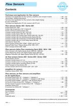
Flow Sensors Contents Technique and application for flow sensors Technique and application for flow sensors, amplifiers and compact models . . . . . . . . . . . . 1.03 - 1.07 Terminology / Setting instructions . . . . . . . . . . . . . . . . . . . . . . . . . . . . . . . . . . . . . . . . . . . . . . . 1.08 - 1.09 Technique and application for flow sensors inline-digital display . . . . . . . . . . . . . . . . . . . . . . . . . . . 1.10 Ex area certification . . . . . . . . . . . . . . . . . . . . . . . . . . . . . . . . . . . . . . . . . . . . . . . . . . . . . . . . . . . . . . . 1.11 Technique...
Open the catalog to page 2
Flow Sensors Technique and application Function The function of the flow controller is based on the thermodynamic principle. The sensor is heated internally a few degrees °C compared to the medium into which it projects. When the medium flows, the heat generated in the sensor is conducted away by the medium, i. e. the sensor cools down. The temperature within the sensor is measured and compared to the temperature of the medium. The state of flow can be derived for each medium by the temperature difference attained. – In metal processing, e.g. rolling mills and wire drawing machines, the rolls...
Open the catalog to page 3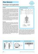
Dimensions of the gasket Thread 3 = Chamber 4 = Edge 5 = Counterpart The temperature-sensitive measuring elements are fitted in the tip of the probe. The probe tip and the adjoining thread/mounting part are made in one piece of stainless steel in many probes. This guarantees absolute tightness and high compressive strength. Special materials are used in corrosive, and particularly in oxidizing media, since stainless steel shows only limited resistance to corrosion in this application. In standard applications, probes can be mounted independently of the direction of flow of the medium. In any...
Open the catalog to page 4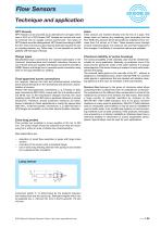
Flow Sensors Technique and application NPT threads NPT threads can be provided as an alternative for all types which have a G1/2 or a G3/4 thread. NPT threads are conical and must be screwed into an equally conical counter-part. Two types of NPT threads must be distinguished. NPT thread according to ANSI B 1.20.1 does not ensure a good seal by itself and requires the use of a sealing medium, e.g. Teflon tape. It is not possible to use flat gaskets with this type of thread. Inline sensors are inserted directly into the line of a pipe. This design does not feature any measuring pins protruding...
Open the catalog to page 5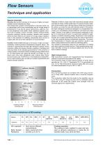
Flow SensorsTechnique and application Special materials Hastelloy B-2 (2.4617) belongs to the group of highly corrosion-resistant nickel-molybdenum alloys. This material has excellent characteristics in reducing media, e.g. in hydrochloric acid of any concentration and for a large range of temperatures. It can also be used in hydrochloric, sulphuric, acetic and phosphoric acid media. Good resistance against corrosion such as pitting, crevice corrosion, chlorine induced stress, corrosion cracking, hair-line corrosion, abrasion and corrosion within the heat influence zone allows for a large range...
Open the catalog to page 6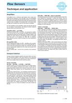
Flow Sensors Technique and application Amplifiers All amplifiers have a multicolour LED display which visually indicates the flow tendency. If the LED light is red, the preinstalled limit value is not reached and the switching output is not activated. The yellow LED indicates that the limit value was reached and the output is active. In addition to the yellow LED, 4 more green LEDs can light up to indicate how much the limit value is exceeded. For the installation of the amplifiers, make sure that the devices are not subject to heat build-up. The distance between adjacent devices should not be...
Open the catalog to page 7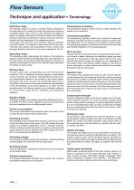
Flow Sensors Technique and application • Terminology Detection range The detection range of a probe or compact device indicates the flow velocities of the medium for which the probe can provide an analysable signal. If the medium is not specified, the details for water are applied. Because the different media have different thermal conductivity, the detection range as well as the temperature drift are also dependent of the respective medium. At the upper and lower limit of the detection range, the temperature drift is higher. The detection range does not limit the maximum flow rate a sensor may...
Open the catalog to page 8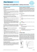
Switching output General • The output is active when the yellow LED is lit. • Set the switching point with the potentiometer at the front of the device. • Keep the flow rate and medium temperature stable during adjustment and wait for the temperature to equalise between the sensor and the medium. • The flow rate must be within the detection rate of the measuring probe. • If present, remove the protective screw M3 x 4 from the potentiometer opening for the duration of configuration. Monitoring a flow limit for being exceeded • Specify the flow rate or stop the flow and wait for the standby time. •...
Open the catalog to page 9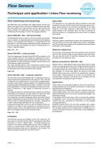
Flow Sensors Technique and application • Inline-Flow monitoring Flow monitoring and measuring Signal filter The EGE-inline flow controllers with digital display monitor flow rates in the range of 0,05...100 l/min and display the flow rate digitally. They feature front panel buttons used to call functions and modify settings. The application area includes all areas of flow monitoring and measuring, in which a flow display is desired. The parameter for the signal filter allows inputting a value that determines the time interval in which the measuring signal is averaged. Inputs between 0 to 8 seconds...
Open the catalog to page 10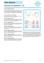
Flow SensorsTechnique and application •Use in hazardous areas Ex marking [A] [B] The EX measurement probes of the 400 meet the basic requirements of Directive 94/9/EC. Electrical boundary data, permissible temperature ranges as well as installation and connection instructions are specified in the operating instructions of EX equipment. Zone classification and categories The frequency and duration of the occurrence of a hazardous atmosphere determines the zone classification. Zone 0 / Category 1 (Gas) Zone 0 is an area in which a potentially explosive atmosphere in the form of a mixture...
Open the catalog to page 11All EGE-Elektronik Spezial-Sensoren GmbH catalogs and technical brochures
 About EGE - Overview
6 Pages
 Flow Sensors
120 Pages
 Accessories M12 Connector
10 Pages
 SDNC 500
2 Pages
 LDS 1000
2 Pages
 LDV 1000
2 Pages
 AGVU
AGVU1 Page
 SDN 550
1 Page
 SCS 440
1 Page
 KBM
KBM1 Page
 Serie cfc
1 Page
 series DN 752
1 Page
 series DGC 075
1 Page
 MFP
MFP1 Page
 TGBA
TGBA1 Page
 Serie AGVU
1 Page
 Serie HGVH
1 Page
 TGM 050 FW T1/T2
1 Page
 GK
GK104 Pages
 Serie IGEXHa
1 Page
 Dust / Gas Series IGEXHa
1 Page
 SDNC500
2 Pages
 SNS 552
2 Pages
 LDN 1000
2 Pages
 SDN 500
2 Pages
 Brochure Pressure-level
8 Pages
 Capacitive Sensors
29 Pages
 Opto high capacity systems
12 Pages
 Series MFP
1 Page
 Series LDN 1000
2 Pages
 Metal detectors
8 Pages
 Ultrasonic Sensors
9 Pages
 Infrared detectors
12 Pages
 Pressure/Level
8 Pages
 demanding environment
16 Pages


Archived catalogs
 Temperature Sensors
12 Pages
 Level Sensors
40 Pages
 Inductive Sensors
72 Pages

- Flowmeter
- Volume flow monitor
- Liquid flow monitor
- EGE proximity sensor
- Level limit switch
- Pressure limiter
- Liquid level detector
- EGE level sensor
- Single-stage pressure regulator
- Stainless steel flow monitor
- EGE liquid level sensor
- Industrial pressure limiter
- EGE cylindrical proximity sensor
- Industrial flow monitor
- EGE inductive proximity sensor
- Membrane regulator
- In-line flow meter
- Water flow monitor
- EGE IP67 proximity sensor