
- Catalogs
- EAO France
- Series 04: Lever Switches - Gessmann


- Company
- Products
- Catalogs
- News & Trends
- Exhibitions
Series 04: Lever Switches - Gessmann

Series 04: Lever Switches - Gessmann
Catalog excerpts

EAO – Your Expert Partner for Human Machine Interfaces Series 04 | Lever Switches Product Information
Open the catalog to page 1
Industrial Controllers Technical Documentation Doc.-Id.: 477100 / 10.01.11 / rd / kraft Subject to technical changes.
Open the catalog to page 3
Industrial Controllers Technical Documentation Modification Report Revision First edition Definition of dimensioned drawings and connecting diagrams in appendix checked and revised – thus automatic change of table of content. 3 § 4.4 – specification for minimal current added § 4.3 – specification for minimal current and specification § 4.3 and § 4.5 – specification for minimal current § 5.1 drawing added (anti-twist device) § 7 drawing numbers revised Attached documents deleted, grip shapes added Revised §7 detents and switching sequences added Document revised construction changed Doc.-Id.:...
Open the catalog to page 4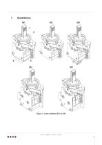
Industrial Controllers Technical Documentation Figure 1: Lever switches S41 to S45 Doc.-Id.: 477100 / 10.01.11 / rd / kraft Subject to technical changes.
Open the catalog to page 6
Industrial Controllers Technical Documentation The lever switches in Figure 1 – types S41 to S45 – are switches, which generate digital output signals depending on the position of the operator handle (1). For this purpose, each switch has a maximum of 5 (S41 to S43) or 4 (S44 and S45) micro-switches (2) with varying switching programs, thus providing for adaptability to the customer’s demands. Besides the switching program, the micro-switch type, the electric interface, the colour of the centering rings (4), and the mechanical features (angle of deflection of the operator handle, form of the...
Open the catalog to page 7
Industrial Controllers Technical Documentation Figure 2 provides information on the lever switch’s basic design features. As one can see, it basically consists of an operator handle (1), which is supported by a flange plate (2). The form of the operator handle can vary. See the dimension drawings of the units (S41 – S45). Below the flange plate, the operator handle is connected with a detent disk (3), which is operated by a spring loaded roller lever (4). This is the operating principle behind the mechanical detent and spring return functions. All of the default detent and spring return functions...
Open the catalog to page 8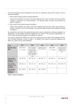
Industrial Controllers Technical Documentation The micro-switches (6) are activated by cam discs (7). Basically, there are two types of microswitches available: 1. Micro-switch without positive opening operation These micro-switches are used in the lever switches S41, S42, and S43. Each lever switch includes a maximum of 5 micro-switches. The technical data of these micro-switches is listed in chapter 4. 2. Micro-switch with positive opening operation These micro-switches are used in the lever switches S44 and S45. Each lever switch includes a maximum of 4 micro-switches. The technical data of...
Open the catalog to page 9
Industrial Controllers Technical Documentation Doc.-Id.: 477100 / 10.01.11 / rd / kraft Subject to technical changes.
Open the catalog to page 10
• Mechanical product life - 5 million cycles • Protection class (front side) - IP 54 Fire behaviour: DIN 5510 - pending *further standards and approbations on request 4.2 Micro-switch without positive opening operation • Mechanical product life - 5 million cycles Micro-switch without positive opening operation (G = gold plated silver contacts) • Mechanical product life - 5 million cycles
Open the catalog to page 11
Industrial Controllers Technical Documentation Micro-switch with positive opening operation • Solder-hook terminated contact with lever switch S44 • Contact with screw terminal with lever switch S45 • contact with blade terminal with lever switch S45 • Mechanical product life • Temperature range • Switching category Minimal current Micro-switch with positive opening operation (G = gold plated silver contacts) • Solder-hook terminated contact • Contact with screw terminal with lever switch S45 • contact with blade terminal with lever switch S45 • Mechanical product life • Temperature range • Switching...
Open the catalog to page 12
Industrial Controllers Technical Documentation Lever switch installation With anti-twist device Without anti-twist device Figure 3 shows the installation of the lever switch. As one can see, the lever switch (1) is inserted into the port (2) from below, and the centering ring (3) is placed upon it from the top. Fix the entire unit by tightening the two attachment screws (4) evenly (NOTE: Max. Torque 50 Ncm!!). Make sure to remove the cylindrical handles (handles 13 and 14) before inserting the lever switch into the port. You will find a detailed instruction for the disassembly of the handles...
Open the catalog to page 13
Industrial Controllers Technical Documentation Handle disassembly The handles 02, 03, 05, 13, 14, and 15 are put over the switching lever and then fixed axially by a hex-socket set screw (M3 DIN 916). Upon the loosening of this set screw, the handles can be removed upwards. For the handles 13 and 14, a cover must be removed first (see fig. 4), before one can access the set screws. When tightening the set screws, make sure not to exceed the max. torque of 20 Ncm. grip cover set screw handle Figure 4: Handle disassembly Type Key contact 2 contact 1 handle design colour of centering ring lock against...
Open the catalog to page 14
Industrial Controllers Industrial Controllers Lever switches S41 to S45 Lever switches S41 to S45 Technical Documentation Technical Documentation Appendix Order, Detents and Switching Sequences (T604) purchase which This appendix includes all and any documents, toorder reference was made inoffer previous the chapters. Company: Type of drawing Data sheet Name: Street Dimensioned drawing Data sheet Zip code: Data sheet Phone: Data sheet Fax: Dimensioned drawing Data sheet E-Mail: Data sheet Order, Detents and switching sequences S4, S41 to S45 Dimensioned drawing S41 Connection diagram 1 to 2 contacts...
Open the catalog to page 15
Industrial Controllers Technical Documentation Appendix Order, Detents and Switching Sequences (T604) purchase which offer This appendix includes all and any documents, toorder reference was made in the previous chapters. Company: Type of drawing Data sheet Name: Street Dimensioned drawing Data sheet Zip code: Data sheet Phone: Data sheet Fax: Dimensioned drawing Data sheet E-Mail: Data sheet Order, Detents and switching sequences S4, S41 to S45 Dimensioned drawing S41 Connection diagram 1 to 2 contacts (S41) Connection diagram, 5 contacts (S41) Connection diagram 3 to 4 contacts (S41) Dimensioned...
Open the catalog to page 16All EAO France catalogs and technical brochures
 data Series 17
1 Page
 BR45
BR4516 Pages
 The Human Touch®
17 Pages
 Series 57 - Indicator
4 Pages
 data Series 45
16 Pages
 data Series 04
13 Pages
 data Series 55
7 Pages
 Series 84. USB 3.0 Sockets.
2 Pages
 Emergency-Stop & Stop Switches
44 Pages
 Série 45
134 Pages
 Series 96: Audio and video
18 Pages
 Series 95: Audio and video
12 Pages
 Industrial Machinery
8 Pages
 Series 57: Public Transportation
16 Pages
 Series 10: Illumination
18 Pages
 Datasheet 82 Series
2 Pages
 Complete QuickSelector
188 Pages
 Transportation Products Catalog
128 Pages
 Audio Video Products Catalog
168 Pages


Archived catalogs

- Single-pole switch
- Push-button switch
- Technology switch
- Multipole switch
- Electromechanical switch
- Rotary electric switch
- Rocker switch
- IP67 switch
- LED indicator light
- Illuminated push-button switch
- Touch push-button switch
- Potentiometer
- Alarm sounder
- Form push-button switch
- Action push-button switch
- Metal switch
- IP65 push-button switch
- Plastic switch
- Manual potentiometer
- Momentary push-button switch