Group: Miya Group

Catalog excerpts
Series 300 Valves Catalogue Series 300 Valves Series 300 Valves Product Catalogue
Open the catalog to page 1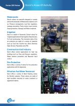
Dorot’s Areas Of Activity Waterworks Dorot’s valves are specially designed to comply with all the demands of Waterworks systems such as: Pressure management, Low flow regulation, Leakage prevention, Pump control, Level control, Surge prevention, Sewage and Water treatment. Irrigation Dorot is a leader in Automatic Control valves for irrigation applications: Drip Irrigation, Greenhouses, Turf and Landscaping. The innovative state of the art products are made of a variety of materials such as: Cast Iron, Ductile Iron, Steel, Stainless Steel, Bronze, Polyamide and uPVC. Construction And...
Open the catalog to page 2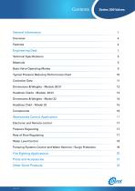
General Information Engineering Data Technical Specifications Basic Valve Operating Modes Typical Pressure Reducing Performance Chart 10 Dimensions & Weights - Models 30/31 12 Headloss Charts - Models 30/31 13 Waterworks Control Application 17 Electronic and Remote control 17 Rate of Flow Regulating 17 Water Level Control 18 Pumping Systems Control and Water Hammer / Surge Protection 19 Fire Fighting Applications 20 Other Dorot Products 23 l^^^^rcONmOL VALVES
Open the catalog to page 3
General Information Overview DOROT’S 300 Series, the latest line of state-of-the-art globe type automatic control valves, is designed to withstand even the most demanding requirements of water system control. The experts at DOROT developed this technically-advanced line with capabilities, far beyond any other valve on the market. This Engineering Data guide will asist the reader in the selection of the optimal DOROT Series 300 valve. Position indicator (optional) Stainless Steel inserts Suspension hook Fully supported Diaphragm Spring Diaphragm discs Double Chamber disc (optional) Fully...
Open the catalog to page 4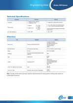
Engineering Data Technical Specifications Parameter • Flanged ISO 7005 or ANSI B16 • Threaded BSP or NPT • Flanged AS10, JIS B22, ABNT and others • 0 min. press. with N.O spring assisted opening. • 0.2 bar / 3 psi min. pressure without a spring Pressure range Note: both options require usage of external higher closing pressure Materials Part Body & Cover Ductile Iron GGG50 (ASTM A-536) Cast Steel A-216 WCB Cast Bronze or Marine Bronze Cast SST CF8M (316) Ni Aluminum Bronze Others Main Valve Internals SST, Bronze and Coated Steel Nylon fabric reinforced EPDM (WRAS and NSF approved) EPDM...
Open the catalog to page 5
Engineering Data Basic Valve Operating Modes On-Off Mode Standard (Single Chamber) Valve Double Chamber Valve (Version D) Closed Mode: The control pressure (taken from the pipeline) is applied by the control device to the control chamber (top of the diaphragm). The pipeline pressure pushes the seal to open, and the control chamber pressure forces the diaphragm to close. Since the diaphragm area is larger than the seal area, it has greater hydraulic force so the valve remains in the closed position. The double chamber version is created by inserting a separation disc between the diaphragm...
Open the catalog to page 6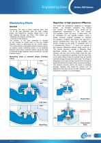
Engineering Data Modulating Mode Modulating Mode General Modulating Mode Positioning the seal a short distance (less than 1/4 of the Regulation at high pressures difference General Modulating Mode seat diameter) from the seat, creates friction and turbulence, Positioning seal a General the loss in short distance (less than 1/4 of the The S-300 has exceptional resistance to damages, causingGeneral energy the fluid passing through the valve. seat diameter) from the seat, creates friction and turbulence, caused by cavitation conditions. This feature The results are: seal a short distance (less...
Open the catalog to page 7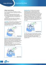
Engineering Data 2-Way Control Device The 2-way control device is assembled on a control circuit, connecting upstream to downstream through the control chamber. There are two restrictors assembled in this circuit: (a) A nozzle or a needle valve, at a fixed opening. (b) A modulating device (pilot), whose passage may vary from complete closure (b=o) to a fully open size (when b>a). The volume of the control media in the chamber is determined by the relative passages (a) and (b), or, in fact, by the opening of (b), as (a) is fixed. Regulating Mode: The pilot is set to the required downstream...
Open the catalog to page 8
3-Way Control Device 3-Way Control Device The 3-way control device The 3-way control device is a small selector valve which: is a small selector valve which: 1. Permits passage of the control media into the 1.Permitsvalve control the control media into the main valve passage of chamber (initiating the “closing” main control chamber (initiating the "closing" procedure), procedure), or or Permits drainage of the control media from the control 2. 2. Permits drainage of the control media from the control chamber to the atmosphere (initiating the “opening” procedure). chamber to the atmosphere...
Open the catalog to page 9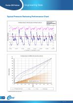
Engineering Data Typical Pressure Reducing Performance Chart Typical Pressure Reducing Performance Chart Actual Site Logging Results Saughton Hall under 10 0mm DOROT 300 S eries CX Pilot Control 100mm Dorot 300 Series CX Pilot Control Pressures logged 1 Pressureslogged atat 1 Minute Intervals MinuteIntervals Flow logged at 15 Minute Flow logged at 15 Minute intervals intervals Flow Litre/sec Flow Litre/sec Pressure Metres Pressure Metres 12.2.2001 Inlet Pressure Inlet Pressure 13.2.2001 Outlet Pressure Outlet Pressure Flow Flow SERIES of CHARACTERISTIC CURVE Comparison 300different seal...
Open the catalog to page 10
Engineering Data Cavitation Data Inlet pressure Inlet pressure psi mwc 360 250 340 Noisy Noisy Operating Operating Destructive Destructive Cavitation Cavitation Safe Safe Operating Operating Conditions conditions Outlet Outlet pressure pressure Cavitation Chart Limits of operating conditions The chart above sets the safe limits for valves that are supposed to operate at a considerable pressure differential. Such conditions generate noise and possible cavitation damages to the valve body. How to use the chart: i. Determine the maximal dynamic pressure that may be applied in the inlet of the...
Open the catalog to page 11All Dorot Control Valves catalogs and technical brochures
-
 DAV-MP-1-KA
2 Pages
-
 Double-Flap Check Valve
1 Pages
-
 Butterfly Wafer Valves
5 Pages
-
 DAV-MP-1-K
2 Pages
-
 DAV-MP-1-A
2 Pages
-
 DAV-WP
4 Pages
-
 DAV MH Series
8 Pages
-
 DAV MS Series
8 Pages
-
 Riser Valves
3 Pages
-
 Galil Hydraulic Valves
3 Pages
-
 Super Gal
8 Pages
-
 60ANC
60ANC2 Pages
-
 uPVC valves
6 Pages
-
 Plastic Valves Catalogue
8 Pages
-
 Series 80 Catalogue
4 Pages
-
 500 Series
12 Pages
-
 GAL Catalogue
44 Pages
-
 Series 100 Catalogue
36 Pages
-
 Angle Irrigation Valves
1 Pages
-
 100 Series
6 Pages
-
 WFDBV-WF/ LU SERIES
6 Pages
-
 Water Meters Catalogue
8 Pages
-
 Turbine Water Meter
2 Pages
-
 Screen Filter (Stone Trap)
2 Pages
-
 Swing check valve
2 Pages
-
 DBV-WF/LU SERIES
6 Pages


