- Catalogs
- Conbraco Industries
- 38-100 SERIES ATMOSPHERIC TYPE VACUUM BREAKER
38-100 SERIES ATMOSPHERIC TYPE VACUUM BREAKER
1 /1Page

38-100 SERIES ATMOSPHERIC TYPE VACUUM BREAKER
1 /1Page
Catalog excerpts

38-100 SERIES ATMOSPHERIC TYPE VACUUM BREAKER Conbraco Industries, Inc. 701 Matthews Mint Hill Rd. Matthews NC 28105 USA; www.apollovalves.com Job Name: Contractor: Job Location: P.O. Number: Engineer: Representative: Tag: Wholesale Distributor: DESCRIPTION The Apollo® 38-100 Series Atmospheric Type Vacuum Breaker is designed to prevent contamination of potable water due to back-siphonage. This 38-100 Series valve is not designed for backpressure conditions or continuous pressure applications of more than 12 hours in a 24 hours period. This Apollo® 38-100 Series valve is recommended for low flow installations that use small amounts of water. Should only be installed in areas where spillage of water would not cause damage. FEATURES • Corrosion resistant bronze body • Compact and easy to maintain • Heat resistant silicone seat disc • Suitable for hot or cold water service • MADE IN THE USA MATERIAL SPECIFICATIONS Part Name Material Body Cast Bronze Seat Disc Silicone Float Gasket Polypropylene Guide Brass Seat Cast Bronze Canopy Chrome-plated Steel Float Polypropylene ORDERING INFORMATION 3 8 – 1 0 X – 0 X SIZE FINISH SIZE ; 704-841-6000 This specification is provided for reference only. Conbraco reserves the right to change any portion of this specification without notice and without incurring obligation to make such changes to Conbraco products previously or subsequently sold. SS1045 © 11/08 Page 1 of 1 00 .. 1 – ¼” .. 2 – ” .. 3 – ½” .. 4 – ¾” .. 5 – 1” .. 6 – 1 ¼” .. 7 – 1 ½” .. 8 – 2” FINISH .. 1 – Rough Brass .. 3 – Rough Chrome .. 4 – Polished Brass .. 6 – Polished Chrome *Note: 1 ¼” - 2” Rough brass only and nitrile o-ring in place of gasket APPROVALS ASSE® 1001, ANSI® A112.1.1, CSA® B64.1.1 and IAPMO® PERFORMANCE RATING Maximum Operating Pressure 125 psig Temperature Range: 33 °F - 212 °F for ¼” thru 1” TemperatureRange:33°F-180°Ffor1¼”thru 2” DIMENSIONS (in.) Size A B C Wt. (lb.) ¼” 2 1 .51 ” 2 1 .48 ½” 1 2 ½ 1 ¼ .55 ¾” 1 3 1 ½ .80 1” 1 ¾ 4 1 1.74 1 ¼” 2 4 2 3.16 1 ½” 2 4 2 2.89 2” 2 4 ½ 2 ¼ 3.69 C B A FLOW CURVES 012345678910020406080100120140Flow Rate (gpm)P r e s s u r e L o s s (p s i)½”¾”1”1 ½”1 ¼”2””¼”
Open the catalog to page 1All Conbraco Industries catalogs and technical brochures
 Backflow Prevention
76 Pages
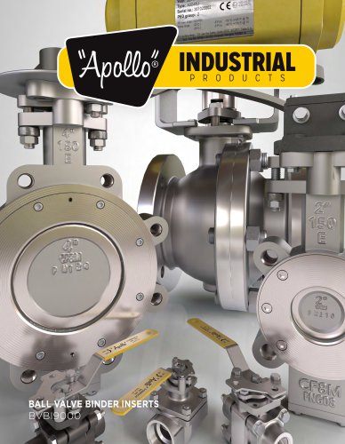 Industrial Products Binder
466 Pages
 Commercial Catalog
292 Pages
 32-100 series
1 Page
 A108
A1082 Pages
 CS & CL SERIES ACTUATORS
3 Pages
 Actuators and Controls
5 Pages
 Industrial Valve
2 Pages
 Gate, Globe & Check Catalog
28 Pages
 Butterfly Valves Catalog
28 Pages
 Backflow Prevention Catalog 2016
76 Pages
 Automatic Control Valves
16 Pages
 APOLLOXPRESS CATALOG
68 Pages
 APOLLOPEX Tools and Valves
4 Pages
 Apollo ® Rack & Pinion
5 Pages
 G series
5 Pages
 LB series
3 Pages
 CS, CL
4 Pages
 PRODUCTS CATALOG
32 Pages
 Top Entry Ball Valve Catalog
44 Pages
 2014/2015 Commercial Catalog
184 Pages
 WATER PRESSURE REDUCING VALVES
20 Pages
 TOP ENTRY BALL VA LV ES
44 Pages
 SAFETY AND RELIEF VALVES
52 Pages
 MIXING VALVES
20 Pages
 Marine Catalog
12 Pages
 Lead Free Products Catalog
71 Pages
 Industrial Ball Valve Binder Inserts
312 Pages
 Fire Protection Products Catalog
20 Pages
 Check Valve Brochure
20 Pages
 Cast Iron Y-Strainer
12 Pages
 77V series 1/2" - 2"
1 Page
 77V series 2-1/2" - 4"
1 Page
 77W-HC series
1 Page
 LB Series Electric Actuators
3 Pages
 TEE
TEE1 Page
 FEMALE ADAPTER
1 Page
 45 DEGREE ELBOW
1 Page
 MALE ADAPTER
1 Page
 Fitting Dimension Sheet
1 Page
 TS_acutorque_2
6 Pages
 cat_PHBRWGA
16 Pages
 cat_PHBRHYD
40 Pages
 cat_GGC9000
28 Pages
 cat_BFFPCAT
20 Pages
 cat_FSCA9000
12 Pages
 cat_ABBR141G
16 Pages
 cat_AXCAT
76 Pages
 cat_ACVBR9000
16 Pages
 cat_ACCA9000
48 Pages
 cat_CICA9000
28 Pages
 cat_CPCA9000
180 Pages
 SERIES 38-500
2 Pages
 THREE-PIECE VALVES
4 Pages
 pipeline strainers
20 Pages
 MARINE VALVES AND FITTINGS
12 Pages
 IN-LINE CHECK VALVES
12 Pages
 CONTROL VALVES
8 Pages
 BACKFLOW PREVENTERS
72 Pages
 BALL VALVES
12 Pages
 ACTUATORS AND CONTROLS
56 Pages


Archived catalogs
 Actuation Catalog
57 Pages
 Class 600 Ball Valve_2015
2 Pages
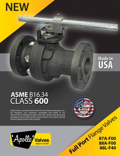 Class 600 Ball Valve_2014
4 Pages
 AE Actuator
4 Pages
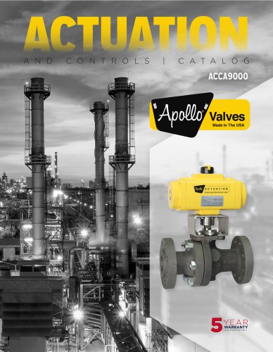 Actuation Catalog ACCA9000
56 Pages
 Conbraco - Catalog
132 Pages
 Conbraco - Strainers CICASTOO
20 Pages


