General Industry Solenoid Valves, Installation & Troubleshooting
1 /2Pages

General Industry Solenoid Valves, Installation & Troubleshooting
1 /2Pages
Catalog excerpts

www.clarksol.com CLARK SOLUTIONS Technical Bulletin, General Industry Solenoid Valves Installation and Troubleshooting MODELS COVERED IN THIS BULLETIN 1314, 1323, 1325, 1327, 1335, 1342, 1365,1390, 1393, 2026, 2036 ELECTRICAL INSTALLATION All the coils are for continuous use - permanent or high frequency operation. Check that the coil supplied with the valve has the correct voltage and current required. If not, replace it with the adequate coil without changing the valve. The allowed voltage variation that does not affect the performance of the valve is -15% to +10% of the nominal voltage for AC and -10% to +10% for DC. Except for valve series 1314, the models are generally supplied with DIN 43650 Connection (ISO 4400) and encapsulated coils. MECHANICAL INSTALLATION Verify that the working conditions are within the range of differential pressure and temperature indi- cated on the nameplate of the valve. ՕPlace a strainer with adequate capacity and a mesh smaller than 100 u immediately upstream from the valve. The most favorable mounting position is on a horizonխtal pipeline with the coil upright. Pipelines upstream from the valve must be carefully and exhaustively cleaned even before the strainer, by means of purges with compressed air or any other system that guarantees the disposal of solid elements as well as welding bits, mud, dirt, etc., especially with new pipelines. Օ Follow the arrow that indicates the flow direction in the valve's body. The input pressure must always be equal or greater than the output pressure. 43650 CONNECT (ISO 4400) INSTRUCTIONS FOR THE ELECTRICAL CONNECTION WITH STRAIN RELIEF 1.Unscrew the screw (8) to reach the block (3), where the terminals are. The system is designed to use armored cables with 3 "PG9" conductors. Carry out Neutral - Live -Ground connections. 2.Insert the terminal block into the cover (4) according to the desired entrance angle, in any of the four possible positions: Left, Right, Above, Below. 3.Insert the coil brades into the connector. Fasten it with the screw (8). 4.Finally but very important, tighten the strain relief (7) to make sure that it is hermetic. Otherwise, moisture may enter and cause a short-circuit between the terminals. INSTRUCTIONS FOR THE COVER WITH AN OPENING FOR Vz NPT CONDUIT. 1.Follow instructions 1, 2 and 3 for strain relief connector. 2.It is important to be sure that the interconnection is hermetic, so we recommend the use of a sealant or gasketing tape over the threads. COIL FIXING The nut (9) that fixes the coil to the core-tube must be 5 Nm / 0.5 kpm / 3.75 lbf, to prevent the coil from turning round. Avoid unnecessary tension that may damage the core-tube due to excess of torsion. 1 Coil 2 Gasket 2a Optional gasket with energized coil indicator light. 3 Electric terminals block. Maximum wire size AWG14 (1.6 mm.) 4 Cover with opening for armored cable. Strain relief "PG9",for cable O.D. from 6 to 8 mm. Cover with indicator light upon request. 4a Cover with opening for conduit. V2 NPT Connection. (Part No 3189-2). Cover with indicator light upon request. 5 Strain relief gasket. 6 Washer. 7 Strain relief. 8 Fixing screw. 9 Coil fixing nut. TROUBLE SHOOTING PROBLEMS Most of the failures that occur when starting a new installation are the result of lack of cleanness in the pipelines between the filter and the valve, due to left-overs of packaging, Teflon, welding residue, dirt, etc.. However, in spite of having made a good choice, a good installation and the adequate maintenance, some contingent factors may occur after the installation and disturb a suitable operation. The following page shows the most common failures with their possible causes and solution. Clark Solutions 10 Brent Drive Օ Hudson, MA 01749 Tel. 978 / 568 3400 Օ Fax 978 / 568 0060
Open the catalog to page 1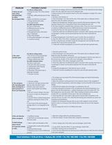
1317.qxp table.main {} tr.row {} td.cell {} div.block {} div.paragraph {} .font0 { font:6.00pt "Lucida Sans Unicode", sans-serif; } .font1 { font:8.00pt "Lucida Sans Unicode", sans-serif; } .font2 { font:10.00pt "Lucida Sans Unicode", sans-serif; } PROBLEM POSSIBLE CAUSES SOLUTIONS For direct acting valves 1. Check the coil voltage, which must not be less than 85% of the indicated nominal voltage. I.Valves do not 1. Voltage less than 15% of the nominal If this is the case, adjust the source to the adequate value. open when voltage. 2. Reduce pressure to the maximum shown on the valve nameplate...
Open the catalog to page 2All Clark catalogs and technical brochures
 Type 525
2 Pages
 Type 520
5 Pages
 Mounting Bracket
1 Page
 9QX Series
2 Pages
 15000 series
1 Page
 BOXER
BOXER2 Pages
 CS-810 Anemometer
1 Page
 RVL Series Vortex Flowmeters
3 Pages
 Clark Sonic Ultrasonic Products
35 Pages


