
Catalog excerpts
CLARK SOLUTIONS Rotary Gear Pumps Technical Bulletin: Pump Slection Information GENERAL PUMP SELECTION Applicable to the handling of all reasonably clean liquids, preferably having some lubricating value. Also suitable for handling nonlubricating liquids under limited conditions of operation with grease fittings or carbon bearings. 1. TYPE OF SERVICE The majority of applications for Clark gear pumps fall into the following categories: (a) Transfer, (b) Lubrica-tion, (c) Hydraulic, (d) Coolant and (e) General. 2. LIQUID TO BE HANDLED Type: Lubricating, corrosive, abrasive or caustic qualities of the liquid to be handled affect selection of pump type and size and its materials of construc魭tion. Specific gravity and viscosity at operating temperature determine speed and horsepower requirements. Lubricity: Rotary Gear pumps depend upon the liquid being cir-culated for lubrication of moving parts. However, the addition of grease fittings will frequently assist in the handling of non-lubricating liquids. Tempͩrature: Operating temperature at the pump is an important factor affecting overall performance. Consideration should be given to any combination of ambient and liquid temperatures plus the heat rise resulting from resistance in the system that will affect the liquid vis-cosity. Generally, the lowest temperature to be encountered should be used to determine power requirements. 3. DELIVERY AND PRESSURE Operating Characteristics: Detailed characteristics over a wide range of operating conditions are given with Specifications and Operating Characteristics for specific pump types. Perͭformance data is based on the specific viscosities given and ratings are for continuous duty. Pump capacities and performance other than those tabu-lated are available to meet a wide range of conditions. Factors in Selection: Determination of the required volume of liquid and operating pressure should include consideration of pipe sizes and pressure losses due to friction and height to which liquid must be raised. 4. SPEED Recommended drive speeds meet standard operating speeds for electric motors and other driving mecha-nisms and are usually applicable for the majority of installations. Considerable variation in operating speed is possible to maintain high efficiency in the handling of a wide range of viscosities. Horsepower: Power requirements should be computed on the basis of highest liquid viscosity and system pressure. Gener-ally, when power requirements fall between standard motor or engine ratings, the larger unit is selected for safety. (See Specifications and Operating Characteris-tics for type of pump to be used.) PUMP SELECTION PROCEDURE STEP1 - Determine Delivery Required in Gallons Per Minute (GPM) and Pressure Required at the Work in Pounds Per Square Inch (PSI). STEP 2 - Determine Pump Inlet Conditions Including Suc-tion Pipe Size and Total Suction Head. STEP3 - Determine Pump Discharge Conditions Including Discharge Pipe Size and Total Head. STEP4 - Select the Pump and Determine Power Required. STEP 1 Convert the quantity of liquid required to gpm and the amount of pressure required at the work to pounds per square inch (psi). Conversion Factors 1 inch of mercury (Hg) equals 1.13 feet of water 15 inches of mercury (Hg) equals 17 feet of water 1 foot of water equals 0.433 pounds per square inch (PSI) 1 pound per square inch (PSI) equals 2.31 feet of water 17 feet of water or 15 inches of mercury equals 7.36 PSI STEP 2 Vertical Lift: Vertical Lift is the amount of pressure required to lift the liquid from its lowest level to the cen-terline of the pump. a) Measure the vertical distance between lowest liquid level and centerline of pump for Distance of Lift. b) Distance of Lift (feet) x Specific Gravity of liquid x 0.433 equals Vertical Lift (PSI) (A maximum Vertical Lift of 7.36 PSI or 15 inches of merͭcury is recommended for normal applications. Higher lifts are permissible with reduced volume. (Contact Clark for recommendations). Suction Pipe Size Having determined that Vertical Lift does not exceed 7.36 PSI, refer to Table 1, Recommended Suction Line Sizes, and select pipe size opposite nearest required delivery and viscosity. To Find Total Suction Head a) Measure entire length of suction pipe including fittings converted to equivalent feet of straight pipe. Refer to Table 2. b) Refer to Table 4, Friction Loss Multipliers, and find the multiplier (M) opposite pipe size and liquid viscosity at delivery required. Total Suction Head (PSI) equals (M x Total feet of suction pipe x Specific Gravity of liquid) plus or minus Vertical Lift (Add Vertical Lift when liquid level is below centerͭline of pump, and Subtract Vertical Lift when liquid level is above centerline of pump). STEP 3 Assume a Discharge Pipe Size the same as Suction Pipe for calculating Friction Head. If smaller pipe is required, liquid velocity should not exceed 10 feet per second. Generally, a Discharge Pipe Size the same as Pump Outlet Connection will prove satisfactory. Total Head a) Find Static Head (measure vertical distance between centerline of pump and highest point of discharge, equals Height of Lift). Static Head (PSI) equals Height of Lift x Spec. Gravity x 0.433 Clark Solutions ו 10 Brent Drive Hudson, MA 01749 Օ Tel. 978 / 568 3400 Fax 978 / 568 0060
Open the catalog to page 1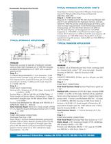
Recommended Max Speed vs Max Viscosity TYPICAL HYDRAULIC APPLICATION CONT'D Total Head = Friction head (16.3 PSI) plus Total Suction Head (7.2 PSI) plus Working Pressure Required (585 PSI)= 608.5 PSI Step 4 PUMP SELECTION Requires 5.17 GPM and 610 PSI. We find that Models 507 and 511 are satisfactory for Hydraulic Service, and are rated for 1000 PSI service while discharge at 0 PSI is suffi-cient to meet requirements. From Performance Data for these pumps, we find the #507 delivers 5.8 GPM at 610 PSI and requires 2.9 horsepower at 1725 RPM. (Capacity at 1140 RPM is insufficient to meet...
Open the catalog to page 3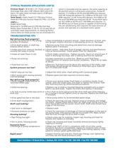
(TYPICAL TRANSFER APPLICATION CONT'D) Friction Head = M (0.04) x 231 (Total Length of Discharge Pipe, plus 2-90° elbows (8.8') plus 0.95 equiv. for gate valve normally open) x 0.88 Spec. Gravity = 8.5 PSI Total Head = Static head (13.7 PSI) plus Friction Head (8.5 PSI) plus Suction Head (0.2 PSI) = 22.4 PSI STEP 4 PUMP SELECTION Required is 14 GPM and 22.4 PSI We find that Rotary Gear Pumps Nos. 3, 3S,13, 23, 53 and 525 all nominally meet requirements. In checking Performance Data for these pumps we can eliminate #13 TROUBLESHOOTING TIPS which is reversible and has approx. the same...
Open the catalog to page 4All Clark catalogs and technical brochures
-
 Type 525
2 Pages
-
 Type 520
5 Pages
-
 Mounting Bracket
1 Pages
-
 9QX Series
2 Pages
-
 15000 series
1 Pages
-
 BOXER
BOXER2 Pages
-
 CS-810 Anemometer
1 Pages
-
 Tubing for Peristaltic Pumps
1 Pages
-
 RVL Series Vortex Flowmeters
3 Pages
-
 Clark Sonic Ultrasonic Products
35 Pages


