- Catalogs
- Changzhou Fulling Motor Co., Ltd
- Brushless DC motor
Brushless DC motor
1 /31Pages

Brushless DC motor
1 /31Pages
Catalog excerpts

Small brushless DC motors_ Principles of opration The diffrences between a DC motor having a mechanical commutation system and a BLDC motor are mainly found in : - the product concept - the commutation of phase currents. From the user 's point of view, brushless DC motors follow the same equations as those with brushes: torque is proportional to current, speed depends on the voltage and the load torque. The commutation of brushless motors In the conventional DC motor commutation takes place mechanically through the commutator-and-brush system. In a BLDC motor, commutation is done by electronic means. In that case the instantaneous rotor position must be known in order to determine the phases to be energized. The angular rotor position can be known by: - using a position sensor (Hall sensor, optical encoder, resolver) - electronically analyzing the back-EMF of a non-energised winding. This is called sensorless commutation. Use of Hall sensors In general, BLDC motor have three phase windings. The easiest way is to power two of them at a time, using Hall sensors to know the rotor position. A simple logic allows for optimal energizing of the phases as a function of rotor position, just like the commutator and brushes are doing in the conventional DC motor. Use of an encoder or resolver The rotor position may also be known by use of an encoder or resolver. Commutation may be done very simply, similar to the procedure with Hall sensors, or it may be more complex by modulating sinusoidal currents in the three phases. This is called vector control, and its advantage is to provide a torque ripple of theoretically zero, as well as a high resolution for precise positioning. Use of Back-EMF analysis A third option requiring no position sensor is the use of a particular electronic circuit. The motor has only three hook-up wires, the three phase windings are connected in either triangle or star. In the latter case, resistors must be used to generate a zero reference voltage. With this solution the motor includes no sensors or electronic components and it is therefore highly insensitive to hostile environments. For applications such as hand-held tools, where the cable is constantly moved, the fact of just three wires is another advantage. The functioning of a sensorless motor is easy to understand. In all motors, the relation of back-EMF and torque versus rotor position is the same. Zero crossing of the voltage induced in the non-energised winding corresponds to the position of maximum torque generated by the two energized phases. This point of zero crossing therefore allows to determine the moment when the following commutation should take place depending on motor speed. This time interval is in fact equivalent to the time the motor takes to move from the position of the preceding commutation to the back-EMF zero crossing position. Electronic circuits designed for this commutation function allow for easy operation of sensorless motors.
Open the catalog to page 1
As the back-EMF information is necessary to know the rotor position, sensorless commutation doesn't work with the motor at stall. The only way of starting is to pilot it at low speed like a stepper in open loop. Remember: - for commutation, position sensors are necessary when operating in incremental mode -sensorless commutation is recommended only for applications running at constant speed and load. Operating principle of BLDC motors: It follows the same equations as the DC motor using mechanical commutation except that parameters like iron losses and losses in the drive circuit are no longer...
Open the catalog to page 2
Brushless DC Motor C FL22RBL SERIES ♦ INDICATIONS OF THE MODELS FL 22 RBL 45 Body length Motor frame size: Metric (mm) RJIrg ♦ GENERAL SPECIFICATIONS ELECTRIC CONNECTION Winding type Star Hall effect angle 120 degree electrical angle Shaft run out 0.025mm Radial play 0.02mm@450g End play 0.08mm@450g Max. radial force 10N @ 10mm from the flange Max. axial force 2N Insulation class Class B Dielectric strength 500VDC for one minute Insulation resistance 100MQMin., 500VDC Lead Lead Lead RUNCTIQN DESCRIPTION No, Color Gauge 1 Blue UL1007 R8AVG Vcc SUPPLY VDLTAGE PDR HALL SENEDRS 2 Red HALL A 3 Yeiiow...
Open the catalog to page 3
Brushless DC Motor FL28BL SERIES ♦ INDICATIONS OF THE MODELS FL 28 BL 38 Body length BuHess neter Motor frame size: Metric (mm) RJlrg ♦ GENERAL SPECIFICATIONS Winding type Star Hall effect angle 120 degree electrical angle Shaft run out 0.025mm Radial play 0.02mm@450g End play 0.08mm@450g Max. radial force 15N @ 10mm from the flange Max. axial force 10N Insulation class Class B Dielectric strength 500VDC for one minute Insulation resistance 100MQMin., 500VDC ELECTRIC CONNECTION Gead Lead Lead FUNCTIDN DESCRIPTION No, Color Gauge 1 Yellow UL10D7 26AVG Vcc SUPPLY VOLTAGE PDR HALL SENEDRS B Blue...
Open the catalog to page 4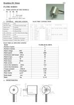
Brushless DC Motor C2 FL33BL SERIES ♦ indications of the models fl 33 bl 38 Body length BuHess neter Motor frame size: Metric (mm) FUllirg ♦ general specifications Winding type Star Hall effect angle 120 degree electrical angle Shaft run out 0.025mm Radial play 0.02mm@450g End play 0.08mm@450g Max. radial force 15N @ 10mm from the flange Max. axial force 10N Insulation class Class B Dielectric strength 500VDC for one minute Insulation resistance 100MQMin., 500VDC electric connection Lead Lead Lead FUNCTIDN DESCRIPTION No, Color Gauge 1 Yellow UL10D7 26AVG Vcc SUPPLY VOLTAGE EQR HALL SENEQRS B...
Open the catalog to page 5
Brushless DC Motor FL42RBL SERIES ♦ indications of the models fl 42 rbl 60 Body length RbudBuHessncba'' Motor frame size: Metric (mm) Fillirg ♦ general specifications electric connection Winding type Star Hall effect angle 120 degree electrical angle Shaft run out 0.025mm Radial play 0.02mm@450g End play 0.08mm@450g Max. radial force 15N @ 10mm from the flange Max. axial force 10N Insulation class Class B Dielectric strength 500VDC for one minute Insulation resistance 100MQMin., 500VDC Lead No, Lead Color Lead Gauge RUNCTIQN DESCRIPTION 1 Blue UL1007 26AVG Vcc SUPPLY VDLTAGP PDR HALL SENEDRS...
Open the catalog to page 6All Changzhou Fulling Motor Co., Ltd catalogs and technical brochures
 BLDC MOTOR SERVO MOTOR
128 Pages
 Frameless Motor -2024
20 Pages
 Driver - 2024
32 Pages
 STEPPER MOTOR
145 Pages
 BLDC Driver S Series
1 Page
 FL80SV SERVO SERIES
2 Pages
 FL60SV SERVO SERIES
2 Pages
 FL86BLS Series
1 Page
 FL57BL(S) SERIES
2 Pages
 FL28BL series
1 Page
 FL22RBL series
1 Page
 1.8° FL39STH series
2 Pages
 1.8° FL35ST series
2 Pages
 1.8° FL20STH series
2 Pages
 Linear Stepping Motor
10 Pages
 PM motor
29 Pages


Archived catalogs
 Fulling Motor
84 Pages
 Motor for MEDICAL
7 Pages

- Electromotor
- Synchronous motor
- Multipole motor
- Electromotor for industrial applications
- 24 V motor
- 4-pole motor
- Servo-motor
- 2-pole motor
- High-efficiency electromotor
- Compact electromotor
- 12 V motor
- Permanent magnet motor
- AC servo-motor
- High-performance servo motor
- High-torque motor
- Stepper motor
- 48 V motor
- Small motor