Oil separators
1 /10Pages

Oil separators
1 /10Pages
Catalog excerpts
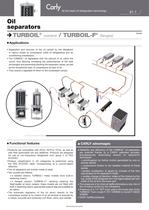
41.1 n Functional features n CARLY advantages Oil separators TURBOIL® (welded) / TURBOIL-F® (flanged) n Applications • Separation and recovery of the oil carried by the refrigerant in vapour phase at compressor outlet of refrigerating and air conditioning installations. • The TURBOIL® oil separators limit the amount of oil within the circuit, thus allowing increasing the performances of the heat exchangers and preventing blocking the expansion valves, as well as the exceptional wear of compressors by lack of oil. • They ensure a regulated oil return to the compressor sumps. C o Products are compatible with HFCs, HCFCs, CFCs, as well as with their associated oils and additives. Products are designed for use of non-hazardous refrigerants from group 2 of PED 97/23/EC. o Product classification in CE categories is performed using the PED 97/23/EC table, corresponding to a volume-based selection. o The oil separators are entirely made of steel. o Two models are offered: a welded version: TURBOIL®; these models have built-in fastening means a flanged version: TURBOIL-F®, allowing cleaning the float/needle oil return system; these models are not fitted with built-in fastening means: appropriate support legs are available as an option. o The automatic regulation of the oil return directly to the compressor sumps or by means of an oil receiver is ensured by a robust, accurate and protected unit (float, valve, and needle). o Reliability and efficiency of the TURBOIL® oil separators are ensured thanks to a CARLY patented process, simultaneously associating several oil separation techniques: centrifugation by helical motion generated by one or several spirals coalescence thanks to the needled material of these spirals sudden modification of speed by increase of the flow area located at the separator’s intake sudden change of direction: intake of the mixture by the top, outlet of the refrigerant from the higher lateral part and outlet of the oil from the lower part. o The presence of an internal baffle eliminates a new risk of the oil being carried by the refrigerant. o Presence of a 1/4” NPT drain plug in the lower part of the TURBOIL® from model F-7011 S/MMS to model F-30025 S/MMS. o GOST certified products. At the heart of refrigeration technology 03/08 Non-binding documents
Open the catalog to page 1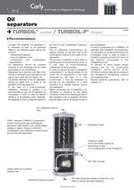
41.2 * To select the TURBOIL® oil separators, it is necessary to refer to the selection tables in the following pages, taking into account: refrigerating capacity type of refrigerant used evaporation and condensation temperatures. * Oil separators should be installed vertically on the discharge line, as close as possible to the compressor. * Refrigerant flow direction with feed from the top is imperative and identified on the upper cover plate with the letters “IN’’. * Connection diameter of the oil separators should be higher than or equal to the diameter of the discharge line. * In the case...
Open the catalog to page 2
41.3 Non-binding documents At the heart of refrigeration technology Oil separators TURBOIL® (welded) / TURBOIL-F® (flanged) n Example of selection C 03/08 Qo Tk 38 = Qo Tk x / {( Tkx - 38) x 0,0143 + 1} Qo Tk 38 = Qo Tk x / {( Tkx - 38) x 0,0143 + 1} • Installation operating with R404A under the following conditions: To = -10°C Tk = 30°C QoTk x = 75 kW Compressor discharge = 1” 5/8 • Which TURBOIL® to choose? (1) Chapter "Abbreviations and units" (refer to chapter 113). The sizing of a product implies for the buyer to take into account the conditions under which the product will be used (temperature...
Open the catalog to page 3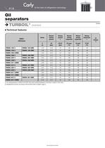
41.6 Non-binding documents At the heart of refrigeration technology Oil separators TURBOIL® (welded) n Technical features C 03/08 (1) The working pressure is limited to the PS BT value when working temperature is lower than or equal to TS BT value. (2) Classification by volume, according to PED 97/23/EC (refer to chapter 0 page 7). CARLY references V (L) PS (bar) PS BT (bar) TS maxi (°C) TS mini (°C) TS BT (°C) Volume Maximal working pressure Working pressure (1) Maximal working temperature Minimal working temperature Working temperature (1) CE Category (2) TURBOIL 1503 S TURBOIL 1503 MMS 1,72...
Open the catalog to page 6
41.7 Non-binding documents At the heart of refrigeration technology Oil separators TURBOIL-F® (flanged) n Selection table C 03/08 (1) The indicated refrigerating capacities take into account a condensation temperature of + 38°C, a 5°C sub-refrigeration, and an aspirated gas temperature of + 18°C. Refer to selection example page 41.3. n Float set internal cleaning or replacement procedure 1 • Isolate the TURBOIL-F® (or the TURBOIL-RF®) 2 • Purge the isolated circuit until atmospheric pressure is reached in the oil separator. 3 • Empty the oil present in the separator, using the 1/4” NPT drain...
Open the catalog to page 7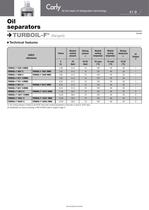
41.9 Non-binding documents At the heart of refrigeration technology Oil separators TURBOIL-F® (flanged) n Technical features C 03/08 (1) The working pressure is limited to the PS BT value when working temperature is lower than or equal to TS BT value. (2) Classification by volume, according to PED 97/23/EC (refer to chapter 0 page 7). CARLY references V (L) PS (bar) PS BT (bar) TS maxi (°C) TS mini (°C) TS BT (°C) Volume Maximal working pressure Working pressure (1) Maximal working temperature Minimal working temperature Working temperature (1) CE Category (2) TURBOIL-F 2505 S/MMS 2,29 31,0 10...
Open the catalog to page 9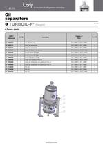
41.10 At the heart of refrigeration technology Oil separators TURBOIL-F® (flanged) C 03/08 n Spare parts Non-binding documents CARLY references Description TURBOIL-F® Types Part Nb Quantity CY 10810010 4 1/4” NPT drain plug 7011 S/MMS to 30025 S/MMS 1 CY 15555151 2 Gasket for oil separator 2505 S/MMS to 3011 S/MMS 1 CY 15555701 2 Gasket for oil separator 7011 S/MMS to 9017 S/MMS 1 CY 15555601 2 Gasket for flange of oil separator 15013 S/MMS to 30025 S/MMS 1 CY 19900420 3 Set of 8 screws for flange 15013 S/MMS to 30025 S/MMS 1 CY 19900425 3 Set of 6 screws for flange 2505 S/MMS to 3011 S/MMS 1...
Open the catalog to page 10All CARLY catalogs and technical brochures


Archived catalogs
 Anti-acid filter driers
8 Pages
 Discharge line mufflers
3 Pages
 Liquid receivers
7 Pages
 Oil filters
2 Pages
 Ball valves
4 Pages
 Filter drier receiver units
3 Pages
 Check valves
5 Pages
 Liquid sight glasses
4 Pages

- Vessel
- Regulating valve
- Liquid filter
- Drying system
- Filter with cartridge
- Metal tank
- Piston actuator valve
- Oil valve
- Pressure separator filter
- Hydraulic valve
- Stainless steel pre-filter
- Industrial tank container
- Cylindrical reservoir
- Centrifugal classifier
- Vertical tank
- Liquids separator
- Y-strainer filter
- Manual test equipment
- Plug valve