Group: Capacitec Us

Catalog excerpts

The Use of Non-Contact Thin Gap Sensors in Controlling Coater Gap Uniformity Written by Bryan Manning Capacitec PO Box 819 Ayer, MA 01432 Tel: 978-772-6033 Fax: 978-772-6036 email: sales@capacitec.com Summary This article will cover the use of capacitive non-contact thin gap sensors in controlling coater gap uniformity The discussion will begin with a description of various coater die gap applications. It will lay out the measurement challenges facing these applications as well as the traditional methods used to measure gaps. Next will be a brief description of capacitive technology. This will be followed by a detailed description of the development of a new capacitive sensor system including specialize sensor wands and customized fixturing, sensor electronics and signal conditioning software. The conclusion will show how the use of this new system has made dramatic improvements over traditional gap measurement methods achieving coater gap uniformity better than 10 microinches (0.25 microns) across the full length of the coater die. Application Description Capacitec has been working closely over the past 10 years with the leading global manufacturers of tapes and films for various commercial and industrial uses. The development was pursued directly with end users as well as with various coater suppliers. The common thread between these users is the utilization of slot extruder dies to apply a variety of very thin chemical, adhesive and photographic coatings to a variety of media. Specific examples of applications include: • • • • Adhesive coatings onto labels Chemical coatings onto films and tapes Photographic coatings onto films Manufacture of plastic tapes In a typical applications the coater die slot gap sizes range from 0.006” (150 microns) to 0.024” (600 microns) with a typical set of slots being 0.006”, 0.008”, 0.010”, 0.012”, 0.014” etc. The length of the slot gap is typically 3 to 6 feet (1 to 2 meters) wide. 1
Open the catalog to page 1
Since there is a direct relationship between setting the width of the slot gap and the thickness of the coating material, it is critical for manufacturers to set a very uniform gap along the full length of the coater die. The uniformity must be held at the microinch level (0.01 microns). (See Figure 1) Figure 1 Gap measurement fixture in the process of measuring coater slot gaps Traditional Measurement Methods In earlier days, manufacturers using old measurement methods were forced to live with gap variations of more than 50 microinches (1.25 microns) over the length of the coater dies....
Open the catalog to page 2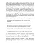
Another traditional method would be to split the extruder die in two and put each half on a granite metrology table. Flatness measurements would then be taken with the use of displacement sensors measuring from above. The next step would be to polish each side to obtain an ideal matched set and bolt the two sides back together. Gap uniformity variations are caused by two factors. The first is a result of variations in the planarity in each half of the die as measured on the table. Additional variability could be seen during re-assembly of the die as a result of variations in the torque...
Open the catalog to page 3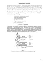
Measurement Solution The benchmark level of less than 10 microinches (0.25 micron) gap uniformity of slot die gaps has recently been accomplished. In fact in some applications it has been exceeded with uniformity being maintained at levels down to 5 microinches. The goal was met after several years’ development with close participation with customers. This next section will describe the steps taken on the road to success. The first step in the solution was the selection of capacitive technology as the basis for sensor design. The choice of capacitive was based on several of its inherent...
Open the catalog to page 4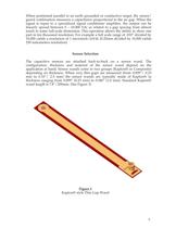
When positioned parallel to an earth grounded or conductive target, the sensor/ guard combination measures a capacitance proportional to the air gap. When the signal is input to a specialized signal conditioner amplifier, the output can be linearly spread between 0 – 10.000 Vdc as related to a gap spacing from almost touch to some full-scale dimension. This operation allows the ability to show one part in ten thousand resolution. For example a full scale range of .010” divided by 10,000 yields a resolution of 1 microinch/mVdc (0.25mm divided by 10,000 yields 250 nanometers resolution)...
Open the catalog to page 5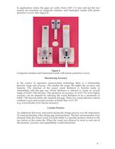
In applications where the gaps are wider (from 0.40”/1.0 mm and up) the two sensors are mounted on composite stainless steel laminated wands with plastic protective covers. (See Figure 4) Figure 4 Composite stainless steel laminated wands with plastic protective covers. Maximizing Accuracy In the science of capacitive measurement technology there is a relationship between range and accuracy. The smaller the range, the higher the accuracy and linearity. The selection of the sensor wand thickness is therefor made in relationship with the gap size. Wand thickness is selected to create an...
Open the catalog to page 6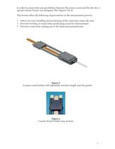
In order to assure best case parallelism between the sensor wand and the die slot, a special custom fixture was designed. (See Figures 5 & 6). This fixture offers the following improvements to the measurement process: • • • Allows for easy handling and positioning of the wand into coater die slots Prevents twisting of wand when positioning wand for measurement Prevents wand from rocking out of the ideal measurement area Figure 5 Custom wand holder with adjustable insertion length and slot guides Figure 6 Custom Wand Holder (top section) 7
Open the catalog to page 7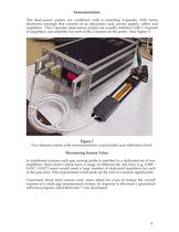
Instrumentation The dual-sensor probes are combined with a matching Capacitec 4100 Series electronics package that consists of an electronics rack, power supply, cables and amplifiers. The Capacitec dual-sensor probes are usually matched with 2 channels of amplifiers, one amplifier for each of the 2 sensors on the probe. (See Figure 7) Figure 7 Two channel system with instrumentation, wand holder and calibration block Maximizing System Value In traditional systems each gap sensing probe is matched to a dedicated set of two amplifiers. Since most Coaters have a range of different die slot...
Open the catalog to page 8All CAPACITEC catalogs and technical brochures
-
 508-SW SWITCHING AMPLIFIER
2 Pages
-
 520 AMPLIFIER
4 Pages
-
 HPC-500
5 Pages
-
 HPC-375
5 Pages
-
 HPC-150
5 Pages
-
 HPC-75
5 Pages
-
 HPT-40
3 Pages
-
 HPB-500
7 Pages
-
 HPB-150
7 Pages
-
 HPB-75
7 Pages
-
 HPB-40
4 Pages
-
 HPC-500
4 Pages
-
 HPC-375
4 Pages
-
 HPC-150
4 Pages
-
 HPC-75
4 Pages
-
 HPC-40
3 Pages
-
 GapmanGen3 Brochure
4 Pages
-
 Coater Bargrafx Software
5 Pages
-
 GAPMANGEN3
4 Pages
-
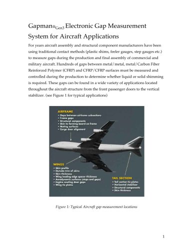
 Aerospace
8 Pages
-
 Capteura® 200 Series System
4 Pages
-
 Slot Die Coater Brochure
4 Pages


Archived catalogs
-
 Disc Brake
4 Pages
-
 Standard products
12 Pages