- Catalogs
- Caddock Electronics
- MP2060 TO-220 Kool-Pak® Clip Mount Power Film Resistor
MP2060 TO-220 Kool-Pak® Clip Mount Power Film Resistor
1 /1Page

MP2060 TO-220 Kool-Pak® Clip Mount Power Film Resistor
1 /1Page
Catalog excerpts
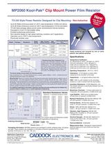
Sales and Corporate Office 1717 Chicago Avenue Riverside, California 92507-2364 Phone: (951) 788-1700 Fax: (951) 369-1151 Applications Engineering 17271 North Umpqua Hwy. Roseburg, Oregon 97470-9422 Phone: (541) 496-0700 Fax: (541) 496-0408 e-mail: [email protected] • web: www.caddock.com For Caddock Distributors listed by country see caddock.com/contact/dist.html © 2004 Caddock Electronics, Inc. C ADKDOC0.410 ± 0.010(10.41 ± 0.26)0.150 ± 0.030(3.81 ± 0.76)0.500 ± 0.050(12.70 ± 1.27)0.035 ± 0.007(0.89 ± 0.18)0.175 ± 0.010(4.45 ± 0.26)0.105 ± 0.010(2.67 ± 0.26)0.100 ± 0.020(2.54 ± 0.51)0.050 ± 0.007(1.27 ± 0.18)0.200 ± 0.010(5.08 ± 0.26)0.640 ± 0.010(16.26 ± 0.26)MP206050.01%MP2060 - 0.050 - 1%Model Number:Resistor Value:Tolerance0.015ÙCurrentLimited0.005ÙMP2060ModelThermal ResistanceRèJCFilm (J) to Case (C)ResistanceMax.Voltage0.020Ù to 1.00KPackageTO-220StyleCurrentLimited250 Vrms6.94°C/Watt2.31°C/Watt2.08°C/Watt60 ArmsMax. CurrentRating (Amps)60 ArmsPowerRating18 Watts *60 Watts *I =P/RCurrentLimited0.010Ù3.47°C/Watt60 Arms36 Watts *54 Watts * MP2060 Kool-Pak® Clip Mount Power Film Resistor 2 5100150CASE TEMPERATURE, °C020401008060RATED POWER % All power and associated overload ratings are derated based upon case temperature using the derating curve. The case temperature is measured at the center of the ceramic mounting surface, with the part properly mounted and under electrical load. Without a heat sink, when in free air at +25°C, the MP2060 is rated for 2.5 watts. The thermal design should satisfy the following equation: Case Temperature (Tc) + [Thermal Resistance (RèJC) x power applied (Watts)] 150°C, considering the full operating temperature range of the application. Mounting Note: Mount on a smooth, clean and flat heat sink surface with a thermal interface material, such as thermal grease. The entire exposed ceramic portion must be in contact with the heat sink. When using a spring clip, it is recommended that a mounting force of 8 to 30 pounds (35 to 130 N) be applied to the center of the package. The clip should be round or smooth in the contact area to avoid concentrating the load on a small point of the plastic body of the package. Another mounting option is to use a pressure bar method which can achieve a greater mounting force with a greater contact area. For additional applications information regarding mounting and pulse handling see the Caddock Applications Notes at caddock.com or contact Applications Engineering. * Derating Using Case Temperature (TC): Derating Curve 0.005 Ù 5% 0.010 Ù 2% 0.015 Ù 2% 0.020 Ù 0.025 Ù 0.030 Ù 0.033 Ù 0.040 Ù 0.050 Ù 0.075 Ù 0.10 Ù 0.15 Ù 0.20 Ù 0.25 Ù 0.30 Ù 0.33 Ù 0.40 Ù 0.50 Ù 0.75 Ù 1.00 Ù 1.50 Ù 2.00 Ù 2.50 Ù 3.00 Ù 3.30 Ù 4.00 Ù 5.00 Ù 7.50 Ù 8.00 Ù 10.0 Ù 12.0 Ù 15.0 Ù 20.0 Ù 25.0 Ù 27.0 Ù 30.0 Ù 33.0 Ù 40.0 Ù 47.0 Ù 50.0 Ù 56.0 Ù 75.0 Ù 100 Ù 120 Ù 150 Ù 200 Ù 250 Ù 300 Ù 330 Ù 400 Ù 470 Ù 500 Ù 560 Ù 750 Ù 1.00 K Standard Resistance Values: Tolerance: 1% Standard (except as noted) For custom values and tolerances contact Applications Engineering Ordering Information: DIMENSIONS IN INCHES AND (MILLIMETERS) Specifications: Temperature Coefficient: TC referenced to +25°C, ÄR taken at +150°C 0.50 ohm and above, -20 to +80 ppm/°C 0.050 ohm to 0.49 ohm, 0 to +100 ppm/°C 0.015 ohm to 0.049 ohm, 0 to +200 ppm/°C 0.005 ohm to 0.014 ohm, 0 to +300 ppm/°C Operating Temperature: -55°C to +150°C Inductance: 10 nH typical in series when measured at the shoulder of the lead. Capacitance: <1 pf typical without heat sink. DWV: 1500 VrmsAC isolation to the mounting surface or a clip in contact with the top surface. Insulation Resistance: 10,000 Megohms, min. The resistor element is electrically isolated from the mounting surface. Momentary Overload: 1.5 times rated power for 5 seconds, ÄR ±(0.5 percent + 0.0005 ohm) max. Load Stability: 2000 hours at rated power ÄR less than ±(1 percent +0.0005 ohm). Moisture Resistance: Mil-Std-202, Method 106, ÄR ±(0.5 percent + 0.0005 ohm) max. Thermal Shock: Mil-Std-202, Method 107, Cond. F, ÄR ±(0.5 percent + 0.0005 ohm) max. Shock: 100G, Mil-Std-202, Method 213, Cond. I, ÄR ±(0.4 percent + 0.0005 ohm) max. Vibration, High Frequency: Mil-Std 202, Method 204, Condition D, ÄR ±(0.4 percent + 0.0005 ohm) max. Terminal Strength: Mil-Std-202, Method 211, Cond. A (Pull Test) 5 lbs., ÄR ±(0.2 percent + 0.0005 ohm) max. Terminal Material: Solderable Measurement Note: Resistance measurements shall be made at 0.2 inch (5.08 mm) from the resistor body. These products are covered by one or more patents, also patents pending. • Up to 60 Watts continuous power at +25°C case temperature, 0.020Ù and above. • Up to 60 Amps continuous current at +25°C case temperature, 0.015Ù and below. • TO-220 Style package utilizes proven power semiconductor thermal solutions. • Equivalent to UL94 V-0 flammability rating. • Excellent pulse/surge performance. • Non-inductive design for high speed switching, snubbers and rf applications. • Operation up to +150°C case temperature. • Electrically isolated case. TO-220 Style Power Resistor Designed for Clip Mounting - Non-Inductive Packaging Information: MP2060 resistors are packaged in plastic shipping tubes, 50 pieces per tube. These resistors are available in a 50 piece minimum quantity and in full tube quantity increments (i.e. 50, 100, 150, etc.). NewClip MountValues to0.005Ù 28_IL128.1004
Open the catalog to page 1All Caddock Electronics catalogs and technical brochures
 Type MS Power Film Resistors
2 Pages


Archived catalogs
 General catalogue
40 Pages


- Wire-wound resistor
- Board-mount resistor
- Housed resistor
- Thin-film resistor
- SMD resistor
- Thick-film resistor
- High-power resistor
- Voltage resistor
- High-voltage resistor
- Non-inductive resistor
- Ceramic-housed resistor
- Precision resistor
- Current-sense resistor
- Axial-lead resistor
- Resistor array
- High-accuracy resistor
- Voltage divider resistor