- Catalogs
- Brooks Instrument
- 5850EM Series
5850EM Series
1 /7Pages
5850EM Series
1 /7Pages
Catalog excerpts

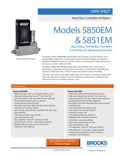
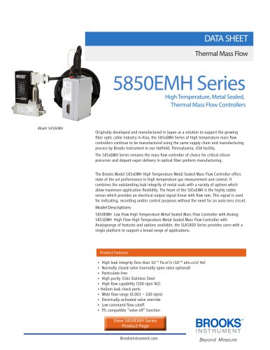
DATA SHEET Mass Flow Controllers & Meters Models 5850EM & 5851EM Metal Sealed, Thermal Mass Flow Meters & Controllers for High-pressure Gas Flows The Brooks® Model 5850EM Metal Sealed Mass Flow Controller has all the features of the standard Model 5850E plus all metal seals for outstanding leak integrity and cleanliness. The Model 5850EM eliminates the need for continuous monitoring and readjustment of gas pressures to provide a stable mass flow. The Brooks® Model 5851EM Metal Sealed Mass Flow Controller offers state-of-the-art performance in high flow gas measurement and control. It combines the outstanding leak integrity of metal seals with a variety of options which allow maximum flexibility. The heart of the system is the highly stable sensor which produces an electrical output signal linear with flow rate. This signal is used for indicating, recording and/or control purposes without the need for an auxiliary auto-zero circuit. Product Features Model 5850EM • Wide flow range (0.06 sccm through 30,000 sccm N2) • High leak integrity (less than 10-10 atm-cc/sec He) • Enhanced process (5 Ra avg.) internal finish (optional) • Electropolished wetted surfaces (optional) • Vented-polished internal threads • Normally Closed Valve (Normally Open Valve optional) • Insensitive to mounting attitude • Mechanically and electrically compatible with other mass flow controllers • Electrically activated valve override • Low command flow cutoff • TTL compatible “valve off” and purge function • 0(4)-20 mA I/O, 24 Vdc, i-Series design (optional) • Available with all popular process connections • Downport C-Seal (optional) Model 5851EM • High flow capability 100 slpm N2(200 slpm H2) • High leak integrity (less than 10-10 atm-cc/sec He) • Enhanced process (5 Ra avg.) internal finish (optional) • Electropolished wetted surfaces (optional) • Normally Closed Valve (Normally Open Valve optional) • Particulate free • High purity VAR 316L Stainless Steel • Fast response to command changes • Helium leak check ports • Class 100 assembly and calibration • Negligible flow overshoot/undershoot • Insensitive to mounting attitude • Electrically activated valve override • Low command flow cutoff • TTL compatible “valve off” and purge function • 0(4)-20mA I/O, 24 Vdc power supply (optional) • Available with all popular process connections • Downport C-Sea
Open the catalog to page 1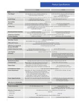
PERFORMANCE Flow Ranges* Any range from 0-3 sccm to -30,000 sccm Nitrogen eq. Lower flows available, consult factory Any full scale flow from 10 slpm to 100 slpm nitrogen eq., up to 200 slpm H2. Higher H2 flows possible, consult factory *Standard pressure and temperature in accordance with SEMI (Semiconductor Equipment and Materials International: Standard: 0°C and 101 kPa (760 Torr). Control Range 2-100% with elastomeric valve seat 50 to 1 with elastomeric valve seat 3-100% with metal or Teflon® valve seat Repeatability Accuracy Settling Time Mounting Attitude Sensitivity Temperature Sensitivity...
Open the catalog to page 2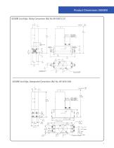
Product Dimensions 5850EM 5850EM Card Edge, Tubing Connections (Ref. No KR-5850-113) 5850EM Card Edge, Downported Connections (Ref. No. KR-5850-106)
Open the catalog to page 3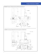
Product Dimensions 5850EM 5850EM D-Connector, Tubing Connections (Ref. No. KR-5850-110) 5850EM D-Connector, Downported Connections (ref. No. KR-5850-103)
Open the catalog to page 4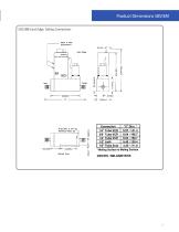
Product Dimensions 5851EM 5851EM Card Edge, Tubing Connections
Open the catalog to page 5
Product Dimensions 5851EM 5851EM D-Connector, Tubing Connections
Open the catalog to page 6
Service and Support Brooks is committed to assuring all of our customers receive the ideal flow solution for their application, along with outstanding service and support to back it up. We operate first class repair facilities located around the world to provide rapid response and support. Each location utilizes primary standard calibration equipment to ensure accuracy and reliability for repairs and recalibration and is certified by our local Weights and Measures Authorities and traceable to the relevant International Standards. Visit www.BrooksInstrument.com to locate the service location nearest...
Open the catalog to page 7All Brooks Instrument catalogs and technical brochures
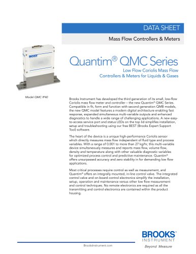 Quantim® Series
9 Pages
 SolidSense II® Series
12 Pages
 Sho-Rate Series
9 Pages
 947N
947N4 Pages
 NRS™ Series
4 Pages
 0260 Series
4 Pages
 0250 Series
8 Pages
 LR-056
4 Pages
 VDM300
4 Pages
 XacTorr® Series
8 Pages
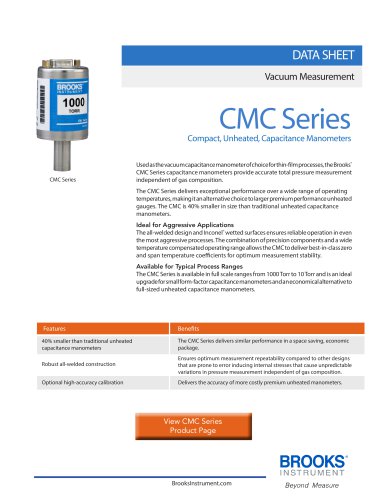 CMC Series
4 Pages
 PC100 Series
4 Pages
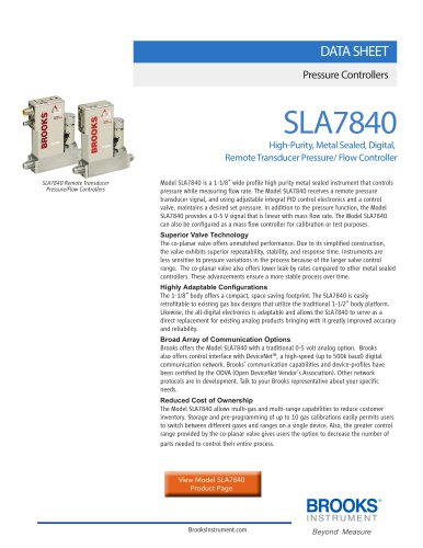 SLA7840
4 Pages
 SLA10/20/40 Series
12 Pages
 5866RT
4 Pages
 122 Series Pressure Gauges
4 Pages
 8600 Series
2 Pages
 MT3809 Series
24 Pages
 MT3750 Series
13 Pages
 FC Series
8 Pages
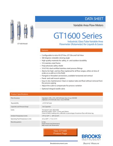 GT1600 Series
11 Pages
 9861 Series
5 Pages
 5850EMH Series
5 Pages
 5850E Series
8 Pages
 GF80 Series
10 Pages
 GF100 Series
12 Pages
 GF100 Series EtherCAT®
9 Pages
 GF125 Series
12 Pages
 5700 Series
4 Pages
 4800 Series
10 Pages
 SLAMf Series
12 Pages
 SLA5800 Series
11 Pages
 GF40 Series
12 Pages


- Manual valve
- Stainless valve
- Display module
- Water valve
- Volume flow monitor
- Liquid flow monitor
- Regulating valve
- Pressure transmitter
- Pressure gauge
- Pressure limiter
- Gas valve
- Analog pressure transmitter
- Waterproof flow meter
- Gas flow monitor
- Single-stage pressure regulator
- Stainless steel flow monitor
- Pressure switch
- Industrial flow monitor