Balanced Receivers
1 /8Pages

Balanced Receivers
1 /8Pages
Catalog excerpts
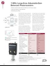
1.16" (29.5) battery check LED photodetectors2x 1.040-32 THDfor mounting Model 1280 Filter Holders and Model 1281 FC Fiber Adapters (not included) output BNCgain-setting switchpower switch 4.06"(103.1) external input power (15VDC) 1.00" (25.4)1.25" (31.8)0.585" (14.9)1.33" (33.8) 8-32 (M4) THD0.58" (14.7) Wavelength Range 4001070 nm 800֖1750 nm > Responsivity,A/W 0.00.20.40.60.81.0 3-dB Bandwidth > 1MHz, 200 kHz, 150 kHz 150 kHz, 30 kHz, 30 kHz > 400800120016002000 Typical Common-Mode Rejection 40 dB 40 dB Wavelength, nm Rise Time 500 ns 3.3 Ƶs > Peak Conversion Gain 1.2 10 > 6 V/W 1.6 ח 10 >...
Open the catalog to page 3All Bookham catalogs and technical brochures
 Explorer One Compact
3 Pages
 843-R
843-R2 Pages
 919P-003-10
2 Pages
 HXP100-ELECV6
2 Pages
 INT1-36-6-A
2 Pages
 15RP52-2
2 Pages
 R-30602
2 Pages


Archived catalogs
 Closed-loop Actuators
6 Pages
 Picomotor™ Actuators
6 Pages
 Beam-Position Photoreceivers
6 Pages
 Power Sensors
4 Pages
 Amplitude Modulators
2 Pages
 Phase Modulators
6 Pages
 Optical Choppers
2 Pages
 Single-Wavelength Lasers
4 Pages
 Multipurpose
6 Pages
 Swept Wavelength
4 Pages
 OEM Tunable Laser Modules
2 Pages


Related Searches
- Positioning table
- Motorized positioning table
- Single-axis positioning stage
- Solid-state laser
- Rotary positioning table
- Visible laser
- Continuous wave laser
- Continuous laser
- Convex array lens element
- OEM laser
- Laser module
- Silica lens element
- Single-mode laser
- Piezoelectric actuator
- Linear piezoelectric actuator
- Direct diode laser
- Monochromatic laser
- Achromatic lens element
- Solid-state laser module
- Infrared sensor
*Prices are pre-tax. They exclude delivery charges and customs duties and do not include additional charges for installation or activation options. Prices are indicative only and may vary by country, with changes to the cost of raw materials and exchange rates.