- Catalogs
- Avago Technologies
- 18 - 36 GHz Double-Balanced Mixer
18 - 36 GHz Double-Balanced Mixer
1 /6Pages

18 - 36 GHz Double-Balanced Mixer
1 /6Pages
Catalog excerpts
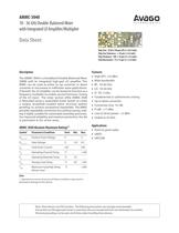
Chip Size: 2520 x 760 m (99.2 x 29.9 mils)Chip Size Tolerance: ձ 10 m (ձ 0.4 mils) Chip Thickness: 100 10 ѵm (4 0.4 mils) Pad Dimensions: 75 x 75 ѵm (3 0.4 mils) The AMMC-3040 is a broadband Double-Balanced Mixer (DBM) with an integrated high-gain LO amplier. This MMIC can be used as either an up converter or down converter in microwave or millimeter wave applications. If desired, the LO amplier can be biased to function as a frequency multiplier to enable second harmonic mixing of the LO input. The mixer section ofthe AMMC-3040 is fabricated using a suspended metal system to create a unique, broadside-coupled balun structure (patent pending) to achieve exceptional bandwidth. The MMIC provides repeatable conversion loss without tuning, mak- ing it highly suitable for automated assembly processes. For improved reliability and moisture protection, the die is passivated at the active areas. ѕ High IIP3: +23 dBm Wide bandwidth Օ RF: 18-36 GHz LO: 18-36 GHz Օ IF: DC-3 GHz Fundamental or subharmonic mixing Օ Up or down converter Conversion loss: 9.5 dB Օ P1dB: +17 dBm Low LO drive power: +2 dBm Օ Usable to 42 GHz > Point-to-point radio Symbol Parameters/Conditions Units Min. Max. Օ LMDS > V D1, 2, 3, 4 Positive Drain Voltage V 5V SATCOM > G1, 2, 3, 4 Gate Voltage V -3.0 0.5I dd Total Drain Current mA 550T ch Operating Channel Temp. հC +160T b Operating Backside Temp. C -55T stg Storage Case Temp. аC -65 +165T max Maximum Assembly Temp. C +300 (60 sec max) Note: 1. Operation in excess of any one of these conditions may result in permanent damage to this device. Note: These devices are ESD sensitive. The following precautions are strongly recommended:Ensure that an ESD approved carrier is used when dice are transported from one destination to another. Personal grounding is to be worn at all times when handling these devices. size="-1">
Open the catalog to page 1
V > D1, 2, 3, 4 Drain Supply Operating Voltage V 2 3.5 5I > d1 First Stage Drain Supply Current, V > dd = 3.5 V, V > g1 = -0.5 V mA 50I > D2, 3, 4 Total Drain Supply Current for Stages 2, 3 and 4 (V > dd = 3.5 V, V > gg = -0.5 V) mA 225V > G1, 2, 3, 4 Gate Supply Operating Voltages (I > dd = 250 mA) V -0.5V > p Pinch-O Voltage (V > dd = 3.5 V, I > dd < 10 mA V -1.5 θ > [2] ch-b Thermal Resistance (Backside Temp. T > b = 25C) аC/W 49 > Notes: 1. Measured in wafer form with T chuck = 25C. (Except Ў ch-bs.)2. Channel-to-backside Thermal Resistance ( ؎ ch-b) = 58ذC/ at Tchannel (Tc)=150C as measured...
Open the catalog to page 2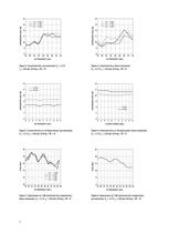
1413 12 11 109 8 1413 12 11 109 8 > LO = 0 dBmLO = 2 dBm LO = 4 dBm LO = 0 dBmLO = 2 dBm LO = 4 dBm CONVERSION LOSS (dB) CONVERSION LOSS (dB) 1820 22 24 26 28 30 3234 1820 22 24 26 28 30 3234 RF FREQUENCY (GHz) RF FREQUENCY (GHz) > d
Open the catalog to page 3
Biasing for Sub-Harmonic Mixing The LO amplier in the AMMC-3040 can also be used as a frequency doubler. Optimum conversion eciency as a doubler is obtained with an input power level of 3 to 8 dBm.Frequency multiplication is achieved by reducing the bias on the rst stage FET to eciently generate har- monics. The remaining three stages are then used to provide amplication. While many bias methods could be used to generate and amplify the desired harmonics within the AMMC- 3040s LO amplier, the following information is sug- gested as a starting point for subharmonic mixing applications. Frequency...
Open the catalog to page 6All Avago Technologies catalogs and technical brochures
 AFCD-V84LP
1 Page
 BCM4778
2 Pages
 AFBR-57H5MZ
29 Pages
 ASMB-UTF0-0D20B
12 Pages
 ASMT-YTD7-0AA02
15 Pages
 ASMT-YTC7-0AA02
15 Pages
 ASMT-RF45-AN002
8 Pages
 Optical Sensor
64 Pages


Archived catalogs
 WLAN Low-Noise Amplifier
10 Pages
 Optoisolation Products
58 Pages
 125 Megabaud Versatile Link
12 Pages
 LED Solutions
96 Pages


- Display module
- Angular encoder
- Incremental encoder
- Incremental rotary encoder
- Switching relay
- Absolute rotary encoder
- Signal amplifying integrated circuit
- Transceiver module
- Optical rotary encoder
- Electronic display panel
- Electronic filter
- Magnetic rotary encoder
- Power amplifying integrated circuit
- Visible LED
- Diode
- Transistor module
- Solid state relay
- GNSS receiver
- Ethernet transceiver
- Data transceiver