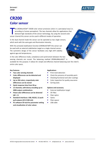
Catalog excerpts
MANUAL CR50 und CR50‐FO ASTECH Angewandte Sensortechnik GmbH Schonenfahrerstr. 5 18057 Rostock Germany Tel.: +49 / 381 / 440 73‐0 Fax: +49 / 381 / 440 73‐20 info@astech.de www.astech.de Vers. 1.0 (2013‐10‐25) 18‐3010‐01
Open the catalog to page 1
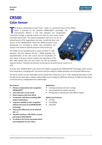
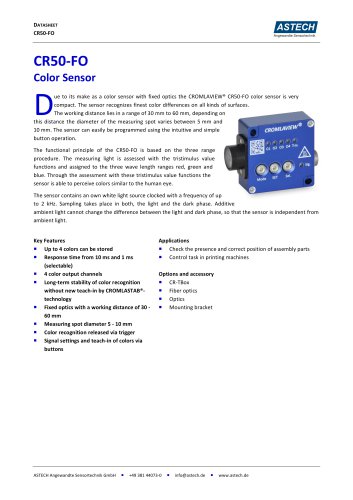
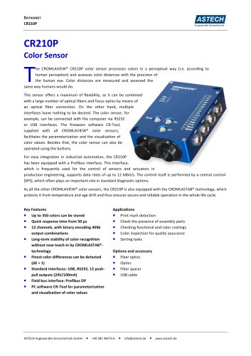
MANUAL CR50 und CR50‐FO Technical Data Table 1: General Data Sensing channels Drift stabilization Receiving detector Sensitivity Sensitivity steps Receiving signal resolution Object illumination Ambient light compensation Standard interfaces Keylock Optional field bus interfaces Displays Buttons Color resolution (L*a*b*) Response time Off‐Delay (channel specific) On‐Delay Hysteresis Color value memory cells Color output channels Protection standard Power supply Case temperature for operation Coupling in signal path Optical fiber adaptation CR50 ...
Open the catalog to page 2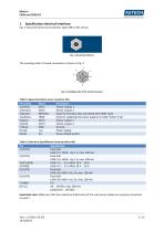
MANUAL CR50 und CR50‐FO Pin (color) 1 (white) 2 (brown) 3 (green) 4 (yellow) 5 (grey) 6 (pink) 7 (blue) 8 (red) Shield Name OUT1 OUT2 KEYLOCK TRG0 OUT3 OUT4 GND +UB SH Description Sensor output 1 Sensor output 1 Input for Key lock, Keys are locked with HIGH‐Level Input for updating the sensor outputs in mode “Extern Trig.” Sensor output 1 Sensor output 1 Ground Power Supply Device Shield (earth) Pin 1 (OUT1) 2 (OUT2) 3 (KEYLOCK) 4 (TRG0) 5 (OUT3) 6 (OUT4) 7 (GND) 8 (+UB) Specification Push‐Pull LOW: 0 V; HIGH: +UB‐1 V; max. 100 mA ...
Open the catalog to page 3
MANUAL CR50 und CR50‐FO
Open the catalog to page 4
MANUAL CR50 und CR50‐FO The sensor is stabilized against thermal drift. With setting of very high power of LED light in connection with a high scanning frequency the temperature will increase and thus drift phenomena may occur. To ensure a safe color recognition, the sensor should be screwed to a heat sink with a heat resistance small than 0.5 K / W. For example this can be a standard aluminum heat sink with the size of 200x200mm with a gill height of 50mm. Large parts of machines also can be used. The sensor can be very hot without using a heat sink. The use of a heat sink is...
Open the catalog to page 5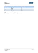
MANUAL CR50 und CR50‐FO Flash impulses Tolerance Tolerance value 1 Very small 3 2 Small 6 3 Medium 9 4 Large 15 5 Very large 20 Note: If the sensor signal is clipping the LEDs are flashing alternately!
Open the catalog to page 6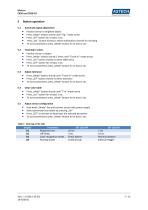
MANUAL CR50 und CR50‐FO Position sensor to brightest object Press „Mode“ button shortly until “Sig.” mode active Press „SET“ button for at least 2 sec. Press „Sel.“ button shortly to select stabilization channel for checking To store parameters press „Mode“ button for at least 2 sec. Teaching in colors Position sensor to object Press „Mode“ button shortly 2 times until “Teach‐In” mode active Press „Sel.“ button shortly to select table entry Press „SET“ button for at least 2 sec To store parameters press „Mode“ button for at least 2 sec. Adjust tolerance ...
Open the catalog to page 7
MANUAL CR50 und CR50‐FO Parts CR50 Color sensor CR50‐FO Color sensor Fiber optical cable Connection cable, 8‐pin, M9/open, 2m M9 protection cap Mounting bracket CR50‐FO / CR100‐FO 6.1 Part numbers 10‐3003‐00 10‐3003‐02 See catalogue (18‐0003‐00) 15‐3000‐00 15‐3010‐00 12‐3000‐00 To use the sensor in systems where the supply voltage line > 3 meters, it is recommended to use a filter module to protect against surges. A suitable 24V DC filter module (surge) is available from the company WAGO under order number 750‐626. Date 28.10.2013 Changes Created
Open the catalog to page 8
Safety instructions The instruments are not to be used for safety applications, in particular applications in which safety of persons depends on proper operation of the instruments. These instruments shall exclusively be used by qualified personnel. Repair only by ASTECH.
Open the catalog to page 9
MANUAL J^T&JZSFl Angewandte Sensortechnik
Open the catalog to page 10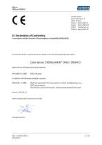
MANUAL CR50 und CR50‐FO ASTECH GmbH Schonenfahrerstr. 5 18057 Rostock Telefon 0381/ 44073‐0 Telefax 0381/ 44073‐20 E‐Mail info@astech.de Internet www.astech.de EC Declaration of Conformity In accordance with the Directive of Electromagnetic Compatibility 2004/108/EG EN 61000‐6‐2:2005 EMC immunity In addition the following standard is passed: EN 61326—1:2006 Electrical equipment for measurement, control and laboratory use – EMC requirements; Classification: Class B (emission), industrial equipment (immunity)
Open the catalog to page 11
MANUAL CR50 und CR50‐FO
Open the catalog to page 12All ASTECH Angewandte Sensortechnik GmbH catalogs and technical brochures
-
 LDS10A
2 Pages
-
 CROMLAVIEW® CR10
1 Pages
-
 VLM500-DG
24 Pages
-
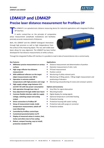 LDM41P and LDM42P
2 Pages
-
 LDM41E and LDM42E
2 Pages
-
 LDM41A and LDM42A
2 Pages
-
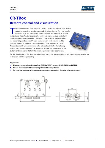 CR-TBox
2 Pages
-
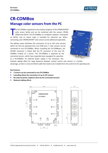 CR-COMBox
2 Pages
-
 CR500
CR5002 Pages
-
 CR50-FO
2 Pages
-
 CR210P
2 Pages
-
 LDS30A
2 Pages
-
 PHSS30x (LDM)
2 Pages
-
 PHSS4x (LDM)
2 Pages
-
 PHSS4x-W (LDM)
2 Pages
-
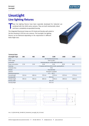 LixusLight
1 Pages
-
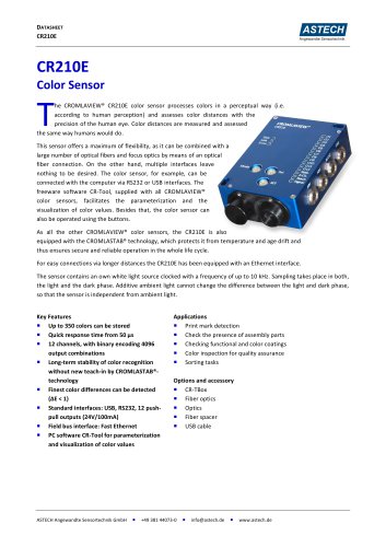 CR210E
2 Pages
-
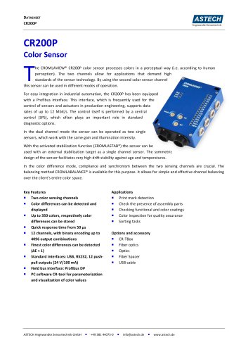 CR200P
2 Pages
-
 CR200E
2 Pages
-
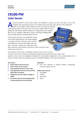 CR100-PM
2 Pages
-
 CROMLAVIEW® CR100 DataSheet
2 Pages
-
 LDM 41/42 P
2 Pages
-
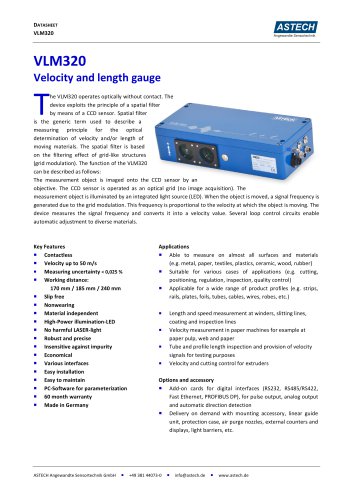 VLM320 Datasheet
2 Pages
-
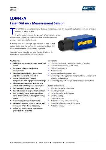 LDM41 A Datasheet
2 Pages
-
 LDM51A LUMOS Datasheet
2 Pages
-
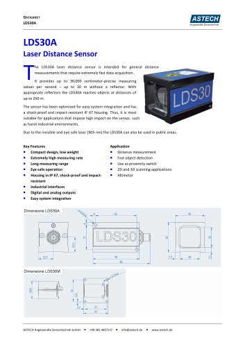 LDS30 Datasheet
2 Pages
-
 FOD-M4.0-1100
4 Pages
-
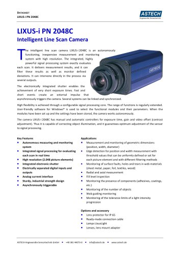 LIXUS-i PN
2 Pages
-
 LDM302A
2 Pages
-
 LDM301A Datasheet
2 Pages
-
 CROMLAVIEW® - Product Catalogue
19 Pages