- Catalogs
- AMETEK Pressure
- 1300 Series Receiver Gauges
1300 Series Receiver Gauges
1 /4Pages

1300 Series Receiver Gauges
1 /4Pages
All AMETEK Pressure catalogs and technical brochures
 Model V534 Canners Gauge
1 Page
 1980
19802 Pages
 1986
19863 Pages
 Product Selection Guide
12 Pages
 TW
TW2 Pages
 Model 8300EX
2 Pages
 Model-HPT-100
4 Pages
 Model-40
9 Pages
 Model_40_Sales_Flyer_001
2 Pages
 Model 575-P
4 Pages
 Model 575
5 Pages
 Model SDT
4 Pages
 Model DDMC
9 Pages
 PMT-LMA-Datasheet
3 Pages
 Sta-Kool-Cooling-Element
2 Pages
 Model-ECPT10
2 Pages
 Model-PST360
2 Pages
 Model-851
4 Pages
 Model 831
4 Pages
 IDT
IDT5 Pages
 Type-SMJ-and-SNJ-Series
2 Pages
 Type-SF-Series
1 Page
 Type-SCE-Series
1 Page
 Type S Series
2 Pages
 Type-R-Series
2 Pages
 P500
P5002 Pages


Archived catalogs
 571
5711 Page
 DT
DT4 Pages
 POC
POC1 Page
 XR
XR2 Pages
 Model TW-STEP Thermowells
2 Pages
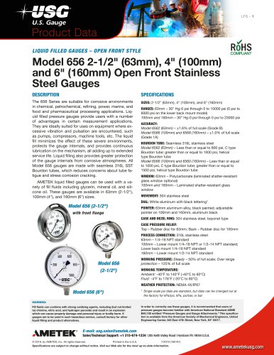
 SOLFRUNT 656 Series Gauges
6 Pages
 SOLFRUNT 659 Series Gauges
5 Pages
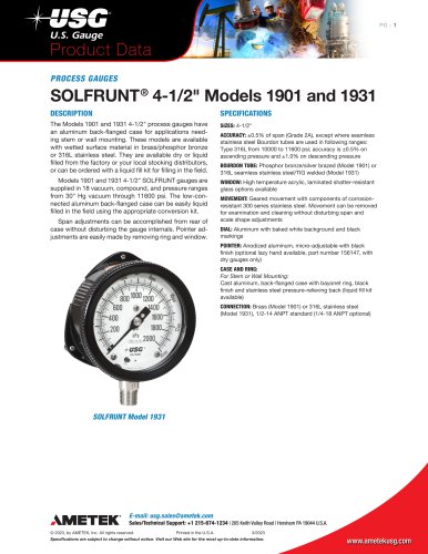
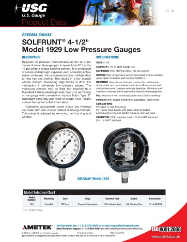
 SOLFRUNT 1900 Series Gauges
17 Pages
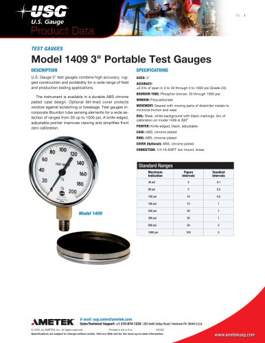
 1400 Series Test Gauges
3 Pages


Related Searches
- Display module
- Surge protector
- Pressure transmitter
- AMETEK pressure gauge
- Analog pressure transmitter
- Level probe
- Liquid level sensor
- Digital pyrometer
- AMETEK analog pressure gauge
- Membrane pressure transmitter
- Stainless steel pressure transmitter
- LED display panel
- Industrial thermometer
- Relative pressure transmitter
- Analog level sensor
- AMETEK °C thermometer
- AMETEK stainless steel pressure gauge
- AMETEK dial pressure gauge
- AMETEK threaded pressure gauge
- AMETEK level transmitter
*Prices are pre-tax. They exclude delivery charges and customs duties and do not include additional charges for installation or activation options. Prices are indicative only and may vary by country, with changes to the cost of raw materials and exchange rates.