- Catalogs
- AMETEK Drexelbrook
- DR7000 Series
- Company
- Products
- Catalogs
- News & Trends
- Exhibitions
DR7000 Series
1 /4Pages

DR7000 Series
1 /4Pages
Catalog excerpts

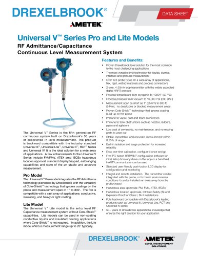
DATA SHEET Designed to Perform Better than any Other Radar Vessel Obstructions Ignored Agitators and other objects such as struts, inlets, ladders, have less effect on signal reduction. The 26GHz FMCW signal is easier to evaluate and the results are more accurate and repeatable. Agitated Surface State-of-the-Art signal processing and a 2GHz bandwidth allow the DR7000 to determine the true level in the tank - even with agitated surfaces. The new DR7000, FMCW 26 GHz radar offers State-of-the-Art components. The DR7000 is able to operate over a larger bandwidth: This ensures sharper resolution and higher accuracy. The higher signal dynamics of the DR7000 allow the accurate detection of even the smallest level changes. The DR7000 is a 2-Wire, Loop Powered, device with an easy navigation display and touch screen user interface which allows for easy configuration and setup. • Easy Navigation Display Choice of different Touch Screens: (tank illustration, bargraph, signal and reflectivity screen) • 2-Wire Class I Div1, Zone 0 Installation • Process Seal Ensures Vessel Integrity • Antenna Types and Materials for all Applications Makes Level Gauging Easier than Ever Wizard Works Wonders Setting up a 2-wire level gauge couldn’t be easier: Simply fit the gauge to the tank, wire it up and switch it on: • Step 1 - The DR7000 tests itself to make sure its electronics are working perfectly. • Step 2 - The DR7000's Wizard walks you through a simple series of questions to define your tank and the product you want to measure. • Step 3 - That’s all you need. Your DR7000 is already measuring. Interactive Help Not certain what to do? You don’t need a handbook. Simply wait 10 seconds, the help screen will appear and tell you what to do.
Open the catalog to page 1
Specifications Input Function Parameter Min. Tank Height Max. Range Dead Zone K-band 26 GHz FMCW radar Level, distance, volume and reflectivity 0.5 m / 1.5 ft 80 m / 262 ft Antenna length + 0.1 m antenna length + 4” Output Signal Output signal Accuracy Resolution Temperature Drift Error Signal Max. Load 4 - 20 mA HART® or 3.8 - 20.5 mA acc. to NAMUR NE 43 0.05% (rel. 20 mA; 20°C / 68°F) ±2 |JA Typically 50 ppm/K High: 22 mA; Low: 3.6 mA acc. to NAMUR NE 43 350 ohm Mechanical Data Housing Wetted Parts Process Fitting Gaskets Process Connection Thread Flange Measuring Accuracy - Reference conditions...
Open the catalog to page 2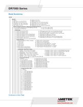
6 FM IS Class I, Div.1 GR. A-G Dual Seal K 7 FM XP Class I, Div.1 GR. A-G Dual Seal M NEPSI Ex ia IIC T3-T6 NEPSI Ex d ia IIC T3-T6 CSA IS Class I, Div1. Div.1 GR A-G Dual Seal CSA XP Class I, Div1. Div.1 GR A-G Dual Seal IECEX Zone 0, Ex ia IIC T3-T6 Ex ia D 20 IECEX Zone 0, Ex d ia IIC T3-T6 Ex t D iaD A21/20 Material of Process Connection / Antenna Type and Material (Pressure) 0 Horn 316SS(1.4404)/40 bar Drop PTFE 40Bar/Drop PP 16bar 2 Horm 316L (1.4404)/ 100 bar G DN 100 Long-OD = 95 mm (3.75”) with Purge System 6 DN 80 Long OD=75mm (2.95”) w/ Purging System U 7...
Open the catalog to page 3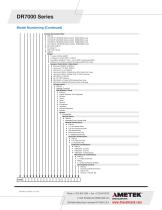
Process Connection Other 0 Without 5 10k 40A RF JIS B2238 Antenna sizes: DN40,DN40-Long 6 10k 50A RF JIS B2238 Antenna sizes: DN50,DN50-Long 7 10k 80A RF JIS B2238 Antenna sizes: DN80,DN80-Long 8 10k 100A RF JIS B2238 Antenna sizes: DN80,DN80-Long C Bio Control DN 50 F Tri-Clamp 2” L DIN 11851 DN 50 P SMS 51 Output 0 1 output 4-20mA (HART) 2 2 Outputs: 4-20mA HART +4-20mA A Foundation Fieldbus 4-Wire + Local HART No Approvals/ATEX D Profibus PA 4-Wire+Local Hart No Approval/ATEX EX ia Only Housing / Cable Entry / Cable Gland 0 Aluminum/ M20x1.5/ Without 1 Aluminum/ 1/2” NPT/ Without 2 Aluminum/...
Open the catalog to page 4All AMETEK Drexelbrook catalogs and technical brochures
 Multipoint II Series
2 Pages
 ClearLine Series
2 Pages
 1500 SERIES RELAY
2 Pages
 7014 and 7010 Series
2 Pages
 Unifloat Level Sensors
9 Pages
 Universal IV ™ CM Model
8 Pages
 Model 375
4 Pages
 Model 575 Series
5 Pages
 Model 575P
4 Pages
 Model 675
5 Pages
 Dumpstar Series
2 Pages
 Plugged Chute Detector
4 Pages
 Universal II Series
2 Pages
 Level Mate III
4 Pages
 Model 575S
5 Pages
 Model SST Slim-Line
4 Pages
 Model SDT
4 Pages
 Total Tank Level System
6 Pages
 Drexelbrook Level Measurement
16 Pages
 DR6300 Series
17 Pages
 DR5200 Series
17 Pages
 Z4-Series
6 Pages
 Universal IV Sales Brochure
10 Pages
 Coal and Fly Ash Solutions
6 Pages
 RXL Series, IntelliPoint
4 Pages


Archived catalogs
 401-400 Series
4 Pages
 Model DDMC
8 Pages
 Accessories Drexelcage
2 Pages
 Point Level
5 Pages
 DR7000
4 Pages
 CM3 Series Cut Monitor
4 Pages
 701X Series Data Sheet
2 Pages
 PNT Series, ThePoint
4 Pages
 Model SDT
4 Pages
 USonic™ Series
4 Pages


- Surge protector
- Digital I/O
- AMETEK level switch
- IO module
- AMETEK liquid level switch
- Level probe
- Liquid level sensor
- Analog I/O
- Switching relay
- Digital IO module
- Float level switch
- Analog level sensor
- Transceiver module
- AMETEK level transmitter
- AMETEK stainless steel level switch
- AMETEK liquid level transmitter
- Electromechanical relay
- Analog IO module
- Serial I/O
- Digital output level sensor