Group: Rockwell Automation

Catalog excerpts

Inductive Proximity Sensors Contents General Information Quick Selection Guide . . . . . . . . . . . . . . . . . . . . . . . page 2--2 Technical Definitions and Terminology . . . . . . . . . page 2--6 Introduction . . . . . . . . . . . . . . . . . . . . . . . . . . . . . . . . page 2--9 Applications . . . . . . . . . . . . . . . . . . . . . . . . . . . . . . . page 2--16 Tubular 871TM All Stainless Steel . . . . . . . . . . . . . . . . . . . page 2--21 872C WorldProxt General Purpose . . . . . . . . . . page 2--47 871T Stainless Steel Barrel . . . . . . . . . . . . . . . . . page 2--85 871TS Food and Beverage . . . . . . . . . . . . . . . . . . page 2--93 871Z Weld Field Immune . . . . . . . . . . . . . . . . . . . page 2--97 871ZT Weld Field Immune . . . . . . . . . . . . . . . . . page 2--103 871C Special Purpose . . . . . . . . . . . . . . . . . . . . . page 2--113 Rectangular 871P VersaCubet . . . . . . . . . . . . . . . . . . . . . . . . 871F Flat Pack . . . . . . . . . . . . . . . . . . . . . . . . . . . 871F Block . . . . . . . . . . . . . . . . . . . . . . . . . . . . . . 871L & 872L Limit Switch Style . . . . . . . . . . . . . 802PR Limit Switch Style . . . . . . . . . . . . . . . . . . 871FM Miniature Flat Pack . . . . . . . . . . . . . . . . . 871P Can Sensors . . . . . . . . . . . . . . . . . . . . . . . . page 2--129 page 2--137 page 2--150 page 2--153 page 2--159 page 2--173 page 2--181 Cylinder Sensors 871D WorldClampt . . . . . . . . . . . . . . . . . . . . . . . page 2--189 871D Cylinder Position . . . . . . . . . . . . . . . . . . . . page 2--195 Ring and Slot 871R Ring & 871S Slot Sensors . . . . . . . . . . . . page 2--201 Accessories Adaptors, Brackets, Covers, Caps, etc. . . . . . . page 2--207 Barriers & Isolators . . . . . . . . . . . . . . . . . . . . . . . . page 12--1 Indexes Cat. No. Index . . . . . . . . . . . . . . . . . . . . . . . . . . . . . page 13--1 Comprehensive Product Index . . . . . . . . . . . . . . . page 14--1 Visit our website: www.ab.com/catalogs. Preferred availability cat. nos. are printed in bold. 2-1
Open the catalog to page 1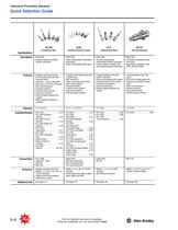
Inductive Proximity Sensors Quick Selection Guide Visit our website: www.ab.com/catalogs. Preferred availability cat. nos. are printed in bold.
Open the catalog to page 2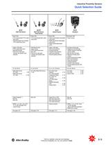
Inductive Proximity Sensors Quick Selection Guide Visit our website: www.ab.com/catalogs. Preferred availability cat. nos. are printed in bold.
Open the catalog to page 3
Inductive Proximity Sensors Quick Selection Guide Flat Pack & Block Limit Switch Style Limit Switch Style Miniature Flat Pack Flat Pack Style • Plastic body Block Style •Aluminum body Limit Switch Style Limit Switch Style • Glass-reinforced polyester housing Miniature Flat Pack Style • Plastic body • Cable, conduit, or QD styles • Short-circuit protection • Overload protection • Transient noise protection • False pulse protection • Reverse polarity protection (DC • 17 sensing head positions (1 top, 16 • Short-circuit protection • Overload protection • Transient noise protection • False...
Open the catalog to page 4
Inductive Proximity Sensors Quick Selection Guide 871P Specifications 871D Can Sensors WorldClamp Description Can Sensor Style • Stainless steel housing/plastic face On-Clamp Cylinder Position Style • Power clamp and gripper style 871D Cylinder Position 871R & 871S Ring & Slot Sensors In-port Cylinder Position Style Ring and Slot Style • Ceramic face/stainless steel probe assembly • Plastic and metal housing Features • Short-circuit protection • Overload protection • Transient noise protection • False pulse protection • Reverse polarity protection (DC models) • Stainless steel housing •...
Open the catalog to page 5
Inductive Proximity Sensors Technical Definitions and Terminology Active Face: Portion of the sensor from which the electromagnetic field or ultrasonic pulse emanates. Axial Approach: The approach of the target with its center maintained on the reference axis. Isolation Voltage: Maximum rated voltage between isolated outputs or input and output. Lateral Approach: The approach of the target perpendicular to the reference axis. Complementary Outputs: (N.O. & N.C.) A proximity sensor that features both normally open and normally closed outputs, which can be used simultaneously. Correction...
Open the catalog to page 6
Inductive Proximity Sensors Technical Definitions and Terminology Shielded Unshielded Visit our website: www.ab.com/catalogs. Preferred availability cat. nos. are printed in bold.
Open the catalog to page 7
Inductive Proximity Sensors 2-8 Vis''our website: www.ab.com/catalogs. /IK „ j. Preferred availability cat. nos. are printed in bold. sggr nHGn~tSr3QlBy
Open the catalog to page 8
Inductive Proximity Sensors Inductive Proximity Sensors Inductive proximity sensors are designed to operate by generating an electromagnetic field and detecting the eddy current losses generated when ferrous and nonferrous metal target objects enter the field. The sensor consists of a coil on a ferrite core, an oscillator, a trigger-signal level detector and an output circuit. As a metal object advances into the field, eddy currents are induced in the target. The result is a loss of energy and a smaller amplitude of oscillation. The detector circuit then recognizes a specific change in...
Open the catalog to page 9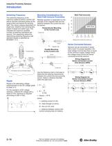
Inductive Proximity Sensors Switching Frequency maximum speed at which a sensor will deliver discrete individual pulses as the target enters and leaves the sensing field. This value is always dependent on target size, distance from sensing face, speed of target and switch type. This indicates the maximum possible number of switching operations per second. The measuring method for determining switching frequency with standard targets is specified by Ripple is the alternating voltage superimposed on the DC voltage (peak switches, a filtered DC voltage with a ripple of 10% maximum is required...
Open the catalog to page 10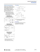
Inductive Proximity Sensors Introduction Parallel Connected Sensors TTL Wiring Sensors can be connected in parallel to energize a load. To determine the maximum allowable number of sensors for an application, the sum of the maximum leakage current of the sensors connected in parallel must be less than the maximum OFF-state current of the load device. ( + ) 10…30V DC Black Sink + Load (--) Common GND ( -- ) ( + ) 10…30V DC TTL Source ( -- ) -- (--) 5V GND V DC + TTL Blue Note: Care should be taken when designing parallel proximity circuits. If too much leakage current flows into the load it...
Open the catalog to page 11All Allen Bradley catalogs and technical brochures
-
 SENSOR-BR001
9 Pages
-
 IA-BR005
64 Pages
-
 937-SG001
70 Pages
-
 937-PP001
4 Pages
-
 931-TD001
52 Pages
-
 931-AT001
2 Pages
-
 931-AT002
4 Pages
-
 Disconnect Switches
7 Pages
-
 Encompass Partner - Stahlin
4 Pages
-
 Encompass Partner - WIN-911
4 Pages
-
 2014 Encompass Product
19 Pages
-
 Essential Components
358 Pages
-
 Operator Interface
54 Pages
-
 RFID
RFID20 Pages
-
 DeviceNet Sensors
18 Pages
-
 Network Media
14 Pages
-
 Connection Systems
46 Pages
-
 Encoders
56 Pages
-
 Capacitive Proximity Sensors
22 Pages
-
 Ultrasonic Sensors
16 Pages
-
 Photoelectric Sensors
334 Pages
-
 Limit Switches
143 Pages
-
 Safety Switches
160 Pages
-
 Lighting Control
26 Pages
-
 Push Buttons
226 Pages
-
 Motor control centers
262 Pages


Archived catalogs
-
 Motors
256 Pages
-
 CENTERLINE® Motor Control Centers
266 Pages
-
 Motor Control Centers
42 Pages
-
 Safety Isolation System
20 Pages
-
 Applied Safety Solutions
10 Pages
