Group: Alfa Laval

Catalog excerpts
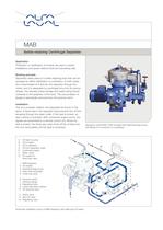
Application Purification or clarification of mineral oils used in marine installations and power stations (fuel and lubricating oils). Working principle Separation takes place in a solids-retaining bowl that can be arranged for either clarification or purification. In both cases, the contaminated oil is fed into the separator through the centre, and it is separated by centrifugal force into its various phases, the heaviest phase (sludge and water) being forced outwards to the periphery of the bowl. The accumulation of sludge is periodically removed from the bowl by hand. Installation The oil is pumped, heated, and separated as shown in the figure. A liquid seal in the separator bowl prevents the oil from escaping through the water outlet. If this seal is broken, an alarm device is activated. With unmanned engine rooms, the signals are transmitted to a remote control unit. When the seal is broken, the three-way valve shuts off the oil feed and the oil is recirculated until the fault is corrected. Separator model MAB 103B complete with feed/discharge pump and fittings for connection to a preheater. MAB Solids-retaining Centrifugal Separator E G 10 12 1 9 5 11 2 13 3 B F 4 6 7 8 D C A A. Oil feed to pump B. Oil to heater C. Oil to separator D. Oil from separator outlet E. Liquid-seal supply F. Water outlet G. Air supply for three-way valve 1. MAB separator 2. Oil strainer 3. Feed/discharge pump 4. Plate heat exchanger 5. Three-way valve 6. Pressure switch 7. Pressure gauge 8. Regulating valve 9. Liquid-seal alarm cabinet 10. Air reducing valve 11. Check valve 12. Shut-off valve 13. Regulating valve Schematic installation layout of MAB separator with plate-type oil heater.
Open the catalog to page 1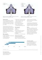
Standard design Solids-retaining separator comprising a frame containing in its lower part a horizontal drive shaft with friction clutch and brake, worm gear and a vertical bowl spindle. The worm gear is placed in an oil bath. The bowl is fixed on the top of the spindle inside the space formed by the upper part of the frame and the frame hood which also carries the feed and discharge systems. The frame hood is hinged to facilitate easy access for cleaning the bowl which is of the solidwall disc type. Basic equipment • Dirty oil inlet device. • Clean oil outlet device with sight glass. •...
Open the catalog to page 2All Alfa Laval catalogs and technical brochures
-
 kyAlfa Laval LeviMag®
11 Pages
-
 PureSOx
12 Pages
-
 Alfa Laval Astepo TAF filler
4 Pages
-
 yAlfa Laval TJ40G
4 Pages
-
 Alfa Laval TJ20G
4 Pages
-
 Alfa Laval AS-H Coplastix®
2 Pages
-
 Heating and cooling systems
160 Pages
-
 Brazed plate heat exchanger
2 Pages
-
 Arctigo HRCD
2 Pages
-
 Heat exchangers
16 Pages
-
 Close at hand, spare parts, January 2016
2016 Pages
-
 LKH UltraPure US 875275
23 Pages
-
 Tri-Clover LKB UltraPure
7 Pages
-
 BDB 104
2 Pages
-
 Product overview
2 Pages
-
 SolidC Centrifugal Pump
2 Pages
-
 Pressosmart
4 Pages
-
 SolarTank
2 Pages
-
 Crushers and depitters
4 Pages
-
 OptiLobe Rotary Lobe Pump
4 Pages
-
 Unique SSV Standard
7 Pages
-
 Alfa Disc
2 Pages
-
 AC232DQ / ACH232DQ
2 Pages
-
 AC112 / ACH112
2 Pages
-
 ISC II
2 Pages
-
 AlfaBlue BXM/BXD
2 Pages
-
 AlfaBlue BCM/BCD & BNM/BND
2 Pages
-
 PureBallast 3.0
6 Pages
-
 Alfa Laval Olmi air cooler
2 Pages
-
 Alcap separation system
4 Pages
-
 Viscosity control system
4 Pages
-
 Pressurisation set
4 Pages
-
 KAB - Sludge filter
2 Pages
-
 AquaTank EM (7bar)
2 Pages
-
 Aquastore
4 Pages
-
 AquaProtect T
2 Pages
-
 Tank Cover
1 Pages
-
 LKS 105 Tank Sight Glass
2 Pages
-
 LKFL In-line Sight Glass
2 Pages
-
 Weighing systems UltraPure
4 Pages
-
 Toftejorg Sanitary Rotacheck
2 Pages
-
 Potentiometric level transmitter
3 Pages
-
 Level switch
3 Pages
-
 Conductivity sensor
4 Pages
-
 Rotary jet mixer IM25
3 Pages
-
 Rotary jet mixer IM20
3 Pages
-
 PD Sheet - Rotary jet mixer IM10
3 Pages
-
 ViscoLine Regenerator Unit
4 Pages
-
 ViscoLine Multitube Unit
4 Pages
-
 ViscoLine MultiPass Unit
4 Pages
-
 ViscoLine Dynamic Unit
4 Pages
-
 ViscoLine Doubletube
2 Pages
-
 ViscoLine CIP Unit
2 Pages
-
 Viscoline Annular Unit
4 Pages
-
 Pharma-line
2 Pages
-
 Water cooled condensers
24 Pages
-
 X20 Application Brochure
12 Pages
-
 S_and_P_Flex_range
9 Pages
-
 PX 95 Disc stack centrifuge
2 Pages
-
 PX 80 Disc stack centrifuge
2 Pages
-
 PX 70 Disc stack centrifuge
2 Pages
-
 PX 65 Disc stack centrifuge
2 Pages
-
 PX 55 Disc stack centrifuge
2 Pages
-
 PX 110 Disc stack centrifuge
2 Pages
-
 Solids ejecting centrifuge
2 Pages
-
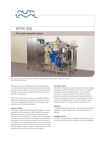 BTPX Separator - BTPX 205
2 Pages
-
 Alfie500
2 Pages
-
 Alfapure2000
2 Pages
-
 AlfaPure Z7
2 Pages
-
 AlfaPure Z3
2 Pages
-
 SolidC UltraPure Centifugal Pump
4 Pages
-
 AlfaCond
2 Pages
-
 NF series
4 Pages
-
 FSM series
3 Pages
-
 Alfa Laval LabUnit M10
2 Pages
-
 FrontLine Plate Heat Exchanger
3 Pages
-
 Fuel Conditioning Module
4 Pages
-
 Lube oil filter T-160 range
4 Pages
-
 Lube oil filter
4 Pages
-
 ALF – Alfa Laval Filter
4 Pages
-
 Alfa Laval Heatpac® Heaters
4 Pages
-
 WS 40, 60
4 Pages
-
 WS 10, 20 ,30
4 Pages
-
 Stnx - decanter centrifuge
4 Pages
-
 SG2 700
2 Pages
-
 Foodec 800
4 Pages
-
 Foodec 600
2 Pages
-
 Foodec 500
4 Pages
-
 Foodec 400
4 Pages
-
 Foodec 300
2 Pages
-
 Foodec 200
2 Pages
-
 Foodec 100
2 Pages
-
 AlfaOliver 500
2 Pages
-
 ALDEC G2 – Smart Decanter
2 Pages
-
 WideGap 350
2 Pages
-
 WideGap 200
2 Pages
-
 TS6 Plate heat exchanger
2 Pages
-
 TS20 - Plate heat exchanger
2 Pages
-
 TL6
TL62 Pages
-
 TL35 - Plate heat exchanger
2 Pages
-
 TL3
TL32 Pages
-
 TL15
TL152 Pages
-
 TL10 - Plate heat exchanger
2 Pages
-
 T50 - Plate heat exchanger
2 Pages
-
 T5 - Plate heat exchanger
2 Pages
-
 T45 - Plate heat exchanger
2 Pages
-
 T20 - Plate heat exchanger
2 Pages
-
 T2 - Plate heat exchanger
2 Pages
-
 MX25 - Plate heat exchanger
2 Pages
-
 M6
M62 Pages
-
 M30 - Plate heat exchanger
2 Pages
-
 M3
M32 Pages
-
 M15
M152 Pages
-
 M10
M102 Pages
-
 PD leaflet: AlfaVap System
2 Pages
-
 AlfaNova 52 / AlfaNova HP 52
2 Pages
-
 AlfaNova 27 / AlfaNova HP 27
2 Pages
-
 AlfaNova 14
2 Pages
-
 Compact frame DOC
2 Pages
-
 CBXP52
2 Pages
-
 CB77
CB772 Pages
-
 CB60 / CBH60
2 Pages
-
 CB52 / CBH52
2 Pages
-
 CB400
CB4002 Pages
-
 CB300 / CBH300
2 Pages
-
 CB27 / CBH27
2 Pages
-
 CB200 / CBH200
2 Pages
-
 CB20
CB202 Pages
-
 CB18 / CBH18
2 Pages
-
 CB16 / CBH16
2 Pages
-
 CB14
CB142 Pages
-
 CB100 / CBH100
2 Pages
-
 AXP14 - Gas cooler
2 Pages
-
 AXP10
AXP102 Pages
-
 Brazed heat exchangers
16 Pages
-
 Spiral HE - General Brochure
16 Pages
-
 AlfaRex - TM20
2 Pages
-
 The hygienic condenser
2 Pages
-
 FK(G) - Gravity coils
2 Pages
-
 Top - Commercial unit cooler
2 Pages
-
 THOR - Industrial air cooler
2 Pages
-
 Airmax II DX - Unit cooler
2 Pages
-
 Centrifugal Unit Cooler ISC
2 Pages
-
 TYR - Industrial air cooler
2 Pages
-
 THOR - Industrial air cooler
2 Pages
-
 AlfaBlue - Power Dry Cooler
2 Pages
-
 Solar Max G - Dry coolers
2 Pages
-
 AlfaBlast
2 Pages
-
 Solar G - Dry coolers
2 Pages
-
 Solar - Air-cooled condensers
2 Pages
-
 Alfa V- Air cooled condenser
2 Pages