- Catalogs
- ALBRIGHT INTERNATIONAL
- SU190 Series of D.C. Contactors
SU190 Series of D.C. Contactors
1 /1Page

SU190 Series of D.C. Contactors
1 /1Page
Catalog excerpts
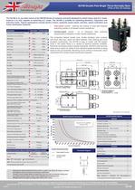
SW150-SW250.pub table.main {} tr.row {} td.cell {} div.block {} div.paragraph {} .font0 { font:4.00pt "Arial", sans-serif; } .font1 { font:5.00pt "Arial", sans-serif; } .font2 { font:6.00pt "Arial", sans-serif; } .font3 { font:7.00pt "Arial", sans-serif; } .font4 { font:9.00pt "Arial", sans-serif; } .font5 { font:11.00pt "Arial", sans-serif; } .font6 { font:12.00pt "Tahoma", sans-serif; } .font7 { font:7.00pt "Times New Roman", serif; } SU190 Double Pole Single Throw Normally Open (Part of the SU Sries) The SU190 is an up-rated variant of the SW190 Series of contactor primarily designed to switch heavy duty D.C. loads, however it is also capable of switching A.C. loads. The SU190 is suitable for switching Resistive, Capacitive and Inductive loads. Typical applications include electric motors, hydraulic power packs, winches, speed controllers and Power Distribution Systems. Interrupted current - opening and closmg on load with fr镩quent switching (results in increased contact rsistance). Application Interrupted Uninterrupted Thermal Current Rating ('th) r 250A 350A ^ Intermittent Current Rating: 30% Duty r 450A 635A ^ 40% Duty r 390A 550A ^ 50% Duty r 360A 495A ^ 60% Duty r 320A 450A ^ 70% Duty r 300A 415A ^ Rated Fault Current Breaking Capacity ('cn) 5ms Time Constant: SU190 ^ 1500A at 48V D.C. ^ SU190B r 1500A at 96V D.C. ^ Rated Fault Current Breaking Capacity ('cn) Resistive Load*: SU190 r 525A at 60V D.C. ^ SU190B r 525A at 96V D.C. a Maximum Recommended Contact Voltages (Ue): SU190 r 96V D.C. a SU190B r 120V D.C. ^ Typical Voltage Drop per pole across New Contacts at 100A r 40mV Mechanical M.T.B.F r >3 x 10⁶ ^ Coil Voltage Available (Us) (Rectifier board required for A.C.) r From 6 to 240V A.C./D.C. Coil Power Dissipation: Very Intermittently Rated Types r 40 - 50 Watts ^ Intermittently Rated types r 30 - 40 Watts ^ Prolonged Rated Types r 15 - 30 Watts ^ Continuously Rated Types r 10 - 15 Watts a Maximum Pull-In Voltage (Coil at 20° C) Guideline: Very Intermittently Rated types (Max 25% Duty Cycle) r 60% Us Intermittently Rated types (Max 70% Duty Cycle) r 60% Us Prolonged Operation (Max 90% Duty Cycle) r 60% Us Continuously Rated Types (100% Duty Cycle) r 66% Us Drop-Out Voltage Range r 10 - 25% ^ Typical Pull-In Time r 30ms ^ Typical Drop-Out Time (N/O Contacts to Open): Without Suppression r 8ms ^ With Diode Suppression r 60ms a With Diode and Resistor 25ms ^ Typical Contact Bounce Period r 3ms ^ Operating Ambient Temperature r - 40°C to + 60°C a Guideline Contactor Weight: SU190 r 760 gms ^ With Auxiliary r + 20 gms ^ With Blowouts r + 50 gms ^ Advised Connection Sizes for Maximum Continuous Current Copper busbar V 161mm2 [0.25inch2] 225mm2 [0.35inch2] A Cable ^Rated suitable for Application j Key: = 'nterrupted = Uninterrupted Note: Where applicable values shown are at 20°C * 'n accordance with UL508 Uninterrupted current - no or infrequent load switching requirements (maintains a lower contact resistance). The contactors feature double pole, double breaking main contacts with silver alloy tips, which are weld resistant, hard wearing and have excellent conductivity. The SU190 is easy to install, with M5 tapped holes in the switch frame or a variety of optional brackets available. Electrical connections follow industry standards, with M10 main terminal studs and an option for either 6.3mm standard spade terminals or flying leads on the coil assembly. Mounting can be vertical or horizontal, when vertical the M10 contact studs should point upwards. 131 [5.151 M5 MOUNTING HOLES (4 OFF PER SIDE) Dimensions in mm [inches] SU190 Available Options General Auxiliary Contacts X Auxiliary Contacts - V3 X Magnetic Blowouts* X Magnetic Blowouts - High Powered* o Armature Cap Mounting Brackets (see SW180 Series Catalogue) o Magnetic Latching (Not fail safe)* o Closed Contact Housing X Environmentally Protected IP66 X EE Type (Steel Shroud) o Contacts Large Tips X Textured Tips o Silver Plating X Coil AC Rectifier Board (Fitted) o Coil Suppression* o Flying Leads o Manual Override Operation X M4 Stud Terminals X M5 Terminal Board o Vacuum Impregnation o Key: Optional o Standard 镕 Not Available X * Connections become polarity sensitive SU190 Contactor Performance 1 1 1 1 1 1 Figures are for guideline - ji pu SCS l_ a" <a* <*> ^ Current (Amperes) Contact Performance Key: Interrupted Current - Uninterrupted Current Performance data provided should be used as a guide only. Some de-rating or variation from figures may be necessary according to application. Thermal current ratings stated are dependant upon the size of conductor being used For further technical advice email: [email protected] Albright reserve the right to change data without prior notice Albright Internbtiona l Ltd, Evingar Trading Estate,Ardglen Road, Whitchurch, Hampshirn, RG28 7BB, UK, Tel: +44 (0)1a56 893060, Fax: +44 (0)1256 893562 Dedicated Sales Tel: +44 (0)1256 890030, Fae: +44 (0)125n 89W)43, E-moil: [email protected]@albrightinternationel.corn Web Site: www.albrightinternational.com v4-08-11 Copyright © 2011 AlbrightInternational LTD SU190
Open the catalog to page 1All ALBRIGHT INTERNATIONAL catalogs and technical brochures
 About Albright
2 Pages
 SU190
SU1901 Page
 DC92 Monoblock, 2 x SW80
1 Page
 DC88P-100
1 Page
 SW61
SW611 Page
 Stud range
7 Pages
 SW80
SW801 Page


Archived catalogs


- Isolator switch
- DC disconnector
- Power contactor
- DC contactor
- Electromagnetic contactor
- AC contactor
- Motor contactor
- High-voltage contactor
- 1 NO contactor
- Reversing contactor
- Contactor for telecom applications
- Normally closed contactor
- Single-pole contactor
- Electromechanical contactor
- NO/NC contactor
- 2-pole contactor
- Capacitor switching contactor
- Power distribution contactor
- Capacitor contactor