- Catalogs
- AIRTEC Pneumatic
- standard cylinder
standard cylinder
1 /19Pages

standard cylinder
1 /19Pages
Catalog excerpts
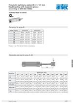
Piston- (mm)ExtensionRetraction32 430 N (96.6 lbf.) 370 N (83.2 lbf.) 40 680 N (152.8 lbf.) 570 N (128.1 lbf.) 50 1060 N (238.3 lbf.) 890 N (200.1 lbf.) 63 1680 N (377.7 lbf.) 1510 N (339.5 lbf.) 80 2700 N (607.0 lbf.) 2550 N (573.3 lbf.) 100 4240 N (953.2 lbf.) 3970 N (892.5 lbf.) 125 6630 N (1490.5 lbf.) 6200 N (1393.8 lbf.) Pressure 6 bar. The internal friction is considered. >
Open the catalog to page 2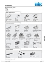
Flexible coupling FK Page 8.203 Foot mount Rod clevis with pin Page 8.202 FD + RD Page 8.018 Sensors h > XLB--06 Page 8.019Swivel mount 90 XLB-ؘ-12 Page 8.017Swivel mount XLB--04 Page 8.017Clevis mount with bushing XLB-ؘ-03 Page 8.016Clevis mount XLB--02 Page 8.016Flange mount XLB-ؘ-01 Page 8.018Trunnion mount XLB--05 Page 8.019 Swivel mount withspherical bearing XLB-ؘ-08 Page 8.020Clevis pin XLB--09 XLB-11 0.5m Rod eye Page 8.221Cover for sensor groove KA- Page 8.020Bearing block Page 8.220Connecting cable XLB-ؘ-10 Trunnion flange mount XLB--11 Page 8.021 Small clevis mount with non rotating...
Open the catalog to page 6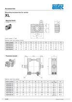
(1 pair) Order number = 1 pair Order numberABCDEFGHIKXLB-032-09 116.6123246157301810.5 XLB-040-09 159163655189362112 XLB-063-09 18112042652011402313 XLB-100-09 201425507525135028.516Material: steel (zinc-plated), bronze >
Open the catalog to page 11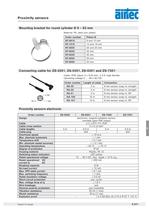
Cable: PUR, black, 3 x 0,25 mm > 2 , l 3.9, high flexibleOperating voltage 0 48 V AC/DC Material: PA, steel zinc plated Order numberLength of cableConnectionKA-30 3 m8 mm sensor snap-in, straight KA-50 5 m8 mm sensor snap-in, straight KA-51 5 m8 mm sensor snap-in, 90 KA-100 10 m8 mm sensor snap-in, straight > BU 34 BK1 BN KA-101 10 m8 mm sensor snap-in, 90а > Order numberZS-6300ZS-6301ZS-7300ZS-7301Design electronic, magnet-induktive sensor,normally open PNP output Cable l 3, LifYY-11Y, PUR Cable cross section 3 x 0.14 mm > 2 Cable lengths 3 m0.3 m3 m0.3 m 8 Cable plug M8֖M8 Overtravel speed...
Open the catalog to page 18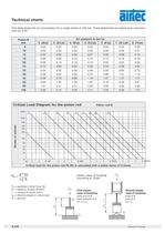
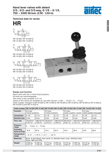
Piston rod-ؘ > Stroke of cylinder Critical load for the piston rod Fk (N) is calculated with a safety factor of 5-times. Elastic cases of buckling according to Eulerē F > k = permitted critical force (N) E > = elasticity module (N/mm 2 ) First elasticcase of buckling l > = moment of inertia (mm 4 ) Second elasticcase of buckling L > k = effective length of critical load open end at Bfixed restraint at A Lk = 2 x L joint at Bjoint at A Lk = L S > = security 8.240 > Subject to change size="-2">
Open the catalog to page 19All AIRTEC Pneumatic catalogs and technical brochures
 Mechanically operated valves
21 Pages
 Series REF-14
12 Pages
 Series E-25
2 Pages
 Series L-25
2 Pages
 Series M-04
14 Pages
 Series SU
1 Page
 Series 84-4F
1 Page
 Series 84-4HF, 84-4HR
2 Pages
 Series TK-28
1 Page
 Series ST-18
1 Page
 Series T-25
5 Pages
 Series HF
1 Page
 Series HV
1 Page
 Series RE-04
3 Pages
 Series RE-19
4 Pages
 Series ICKN-55
4 Pages
 Series KNX-55
4 Pages
 Series PNX-55
2 Pages
 Series M-07
10 Pages
 Series BP-01 and BP-02
3 Pages
 Series E-28
1 Page
 basic line Valves and Cylinders
62 Pages
 T series
12 Pages
 HF series
2 Pages
 ER series
1 Page
 EL series
1 Page
 E series
2 Pages
 Hand lever valves
2 Pages
 ST series
1 Page
 F series
1 Page
 AIRTEC_System_IMA_EN
8 Pages
 54-ATEX-03rev08
1 Page
 54-ATEX-02rev06_111206
5 Pages
 54-SIL-02rev05
1 Page
 54-SIL-02_rev06_120612
1 Page
 GB RE-44
5 Pages
 54-Produkte-01_111216(1)
2 Pages
 AIRTEC Classic ejectors
3 Pages
 Roller-operated valves
2 Pages
 Stem-operated valves
2 Pages


Archived catalogs
 Series XG cylinder
13 Pages
 AIRTEC Column ejectors
32 Pages
 AIRTEC Central ejectors
20 Pages

- Valve
- Control valve
- Stainless valve
- Water valve
- Ball valve
- Pneumatic valve
- Threaded valve
- Regulating valve
- Flange valve
- Flap valve
- Check valve
- ISO valve
- Directional control valve
- Pressure limiter
- Double-acting cylinder
- Pneumatically-operated valve
- Single-stage pressure regulator
- Valve for industrial applications
- Pneumatic cylinder