Position Sensing Configurations for Airpel® Cylinders
1 /1Page

Position Sensing Configurations for Airpel® Cylinders
1 /1Page
Catalog excerpts
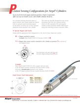
For customers desiring electrical output of piston position, most Airpel models are offered with an optional switch-activating magnet on the piston, as well as one or more optional aluminum tracks attached to the cylinder. The tracks are specially designed for easy, securemounting of the Sick, Inc. position sensors which we offer separately. We stock popular models of these extremely reliable GMR sensors along with matching accessory extension cables. > Simply add the appropriate letter designator(s) to the end of a basic Airpel part number. M= Magnet attached to pistonExample: Basic Model E16D1.5U becomes E16D1.5U MT#= Magnet plus sensor track(s) attached to the cylinder at position T# as shown inthe diagram below. T1 View from front (rod end) with front andrear ports aligned along position T4 T2 T1 axis T3 > Basic Airpel model E16D1.5U with a magnet and one track at the 90 degree position (clockwise) becomes E16D1.5U T2 and with a second track attached to the cylinder at the 270 degree position the part number becomes E16D1.5U T2T4 > 9.51 mm[0.375 in]6.83 mm[0.269 in]OVERALLHEIGHT ModelOverall Height E9/M920.3 mm (0.80 in.) Sensors sold separately. E16/M1627.0 mm (1.06 in.) E24/M2438.2 mm (1.51 in.) Airpot ή and Airpel are registered trademarks of Airpot Corporation. Ω2004 Airpot Corporation Corporation ACS-12K-2 Airpel Division, 35 Lois Street, Norwalk, CT 06851 1-800-848-7681 Fax: 203-849-0539 E mail :[email protected] size="-2">
Open the catalog to page 1All Airpot catalogs and technical brochures
 PFRN1-1 SFRN1-1
1 Page
 airpot-gripper
2 Pages
 Airpot Transducer
1 Page
 Airpel-FFR
8 Pages
 Accurate Force Pneumatics
16 Pages
 Airpel -AB
4 Pages
 The Complete Book of Airpot
58 Pages


- Actuator
- Linear actuator
- Double-acting cylinder
- Pneumatic cylinder
- Pneumatic gripper
- Linear position transmitter
- Single-acting cylinder
- Piston cylinder
- Parallel gripper
- 2-jaw gripper
- Shock buffer
- No-contact position sensor
- Mechanical buffer
- Pneumatic actuator
- Magnetic position sensor
- Industrial buffer
- Anti-vibration damper
- Precision cylinder