
Catalog excerpts
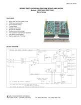
ZBDC12A Series SERIES ZBDC12A BRUSHLESS PWM SERVO AMPLIFIERS Models: ZBDC6A6, ZBDC12A8 Micro Series FEATURES: • • • • • • • • • • Micro size, low cost, ease of use PWM input commands For brushless motors Torque Mode Closed current loop No pots or switches Surface-mount technology Four quadrant regenerative operation Hall sensor commutation Agency approvals: Pending BLOCK DIAGRAM: ADVANCED MOTION CONTROLS 3805 Calle Tecate, Camarillo, CA 93012 Tel: (805) 389-1935, Fax: (805) 389-1165
Open the catalog to page 1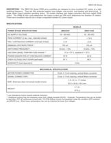
ZBDC12A Series DESCRIPTION: The ZBDC12A Series PWM servo amplifiers are designed to drive brushless DC motors at a high switching frequency. They are fully protected against over-voltage, over-current, over-heating and short-circuit. A single digital output indicates operating status. All models interface with digital controllers that have digital PWM output. The PWM IN duty cycle determines the output current and DIR input determines the direction of rotation. These servo amplifiers require only a single unregulated isolated DC power supply. SPECIFICATIONS: MODELS POWER STAGE...
Open the catalog to page 2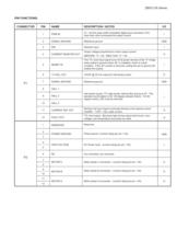
ZBDC12A Series PIN FUNCTIONS: CONNECTOR PIN NAME DESCRIPTION / NOTES 1 PWM IN 10 – 25 kHz pulse width modulated digital input command (+5V). Input duty cycle commands the output current. 2 SIGNAL GROUND Reference ground 3 DIR Direction input 4 CURRENT MONITOR OUT I/O I GND I Output voltage proportional to motor output current: ZBDC6A6: 1V = 2A; ZBDC12A8: 1V = 4A 5 6 +V HALL OUT +6VDC @ 30 mA output for Hall sensor power 7 SIGNAL GROUND Reference ground 8 HALL 1 9 HALL 2 10 HALL 3 11 P1 INHIBIT IN This TTL level input signal turns off all power devices of the “H” bridge when pulled to ground...
Open the catalog to page 3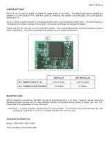
ZBDC12A Series JUMPER SETTINGS: Pin P1-5 can be used to enable or disable the power output to the motor. The default logic level to disable this amplifier is a LOW signal at P1-5. With the jumper JE1 removed, the amplifier will be disabled until a LOW signal is applied to P1-5. JE2 is a jumper to select between a 120-degree phased motor and a 60-degree phased motor. The default setting is 120-degree commutation phasing. Removing the JE2 jumper will change the setting to 60-degree. Please note that JE1 and JE2 are very small SMT jumpers. Only qualified technicians are recommended to perform...
Open the catalog to page 4All Advanced Motion Controls catalogs and technical brochures
-
 dc201e60a40nac
12 Pages
-
 dpcania-060a400
11 Pages
-
 dpcantr-015b200
10 Pages
-
 dprnlie-060a800
11 Pages
-
 dr100ee15a40nac
7 Pages
-
 dr101ee30a40ndc
7 Pages
-
 dzxralte-040l080
8 Pages
-
 mc1xdzc02-qd
9 Pages
-
 ps50a
ps50a4 Pages
-
 se10a40
8 Pages
-
 srst400
4 Pages
-
 sx30a8
8 Pages
-
 zbh6a6
9 Pages
-
 z6a6
z6a65 Pages
-
 zdr150ee12a8ldc
12 Pages
-
 z12a8
z12a85 Pages
-
 25a17
25a172 Pages
-
 20a20
20a209 Pages
-
 Mounting Card MC1XDZ01
13 Pages
-
 INDUCTIVE FILTER CARDS
9 Pages
-
 PS16 SERIES
5 Pages
-
 PS2X3 and PS4X3 SERIES
5 Pages
-
 PS300 SERIES
4 Pages
-
 DPQNNIE-020B080
10 Pages
-
 DPCANTE-020B080
10 Pages
-
 Analog Servo Drive S16A8
8 Pages
-
 Analog Servo Drive BE15A8-H
8 Pages
-
 Analog Servo Drive 12A8
9 Pages
-
 Analog Servo Drive AZ6A8
7 Pages


Archived catalogs
-
 Capabilities Brochure
6 Pages